Evaluating Biosensor Analytical Figures of Merit: A Comprehensive Guide for Precision Diagnostics and Drug Development
This article provides a systematic framework for researchers, scientists, and drug development professionals to evaluate the key analytical figures of merit for biosensors.
Evaluating Biosensor Analytical Figures of Merit: A Comprehensive Guide for Precision Diagnostics and Drug Development
Abstract
This article provides a systematic framework for researchers, scientists, and drug development professionals to evaluate the key analytical figures of merit for biosensors. It explores the foundational principles of performance metrics, including sensitivity, precision, response time, and manufacturability. The scope covers methodological approaches across electrochemical, optical, and genetically engineered biosensors, detailing their application in clinical diagnostics, environmental monitoring, and therapeutic development. It further addresses critical troubleshooting strategies for nonspecific binding and signal optimization, and outlines robust validation and comparative analysis protocols against gold-standard methods. By synthesizing current advancements and practical guidelines, this work aims to enhance the development and deployment of reliable biosensing technologies for precision medicine.
Core Principles: Defining and Measuring Key Biosensor Performance Metrics
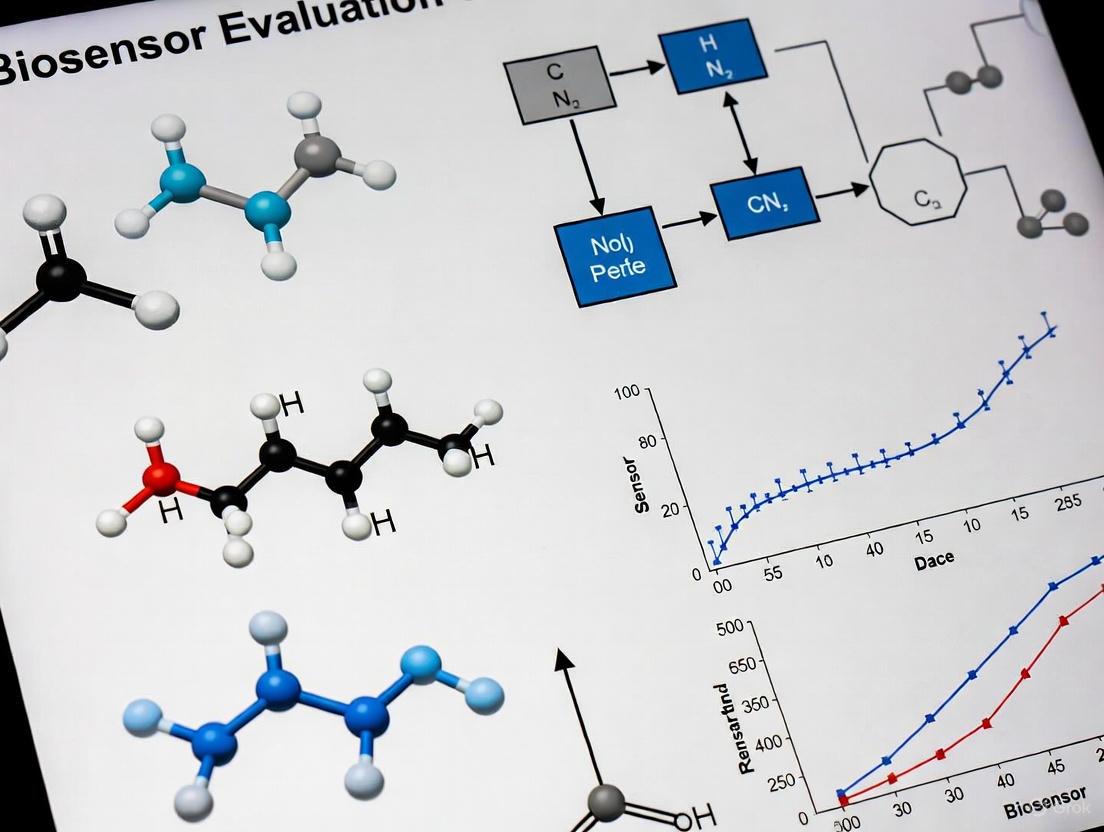
The development and evaluation of biosensors rely on a set of quantifiable, performance-based characteristics known as figures of merit. These parameters provide researchers and developers with standardized metrics to objectively assess and compare the analytical performance of different biosensing platforms [1] [2]. In clinical diagnostics, environmental monitoring, and bioprocess control, the reliability of a biosensor is fundamentally determined by how well it performs against these critical benchmarks. The most essential figures of merit include sensitivity, precision, response time, and the limit of detection (LOD), each providing unique insight into a specific aspect of biosensor functionality [3]. A comprehensive understanding of these metrics is crucial not only for technological development but also for ensuring that a biosensor is fit for its intended real-world application, where factors like complex sample matrices and operational constraints can significantly impact performance [4].
This guide provides a comparative overview of these core figures of merit, supported by experimental data and methodologies from recent research. It also explores the emerging role of advanced materials and machine learning in pushing the boundaries of biosensor performance.
Core Figures of Merit: Definitions and Comparative Analysis
The table below defines the four core figures of merit and their significance in biosensor evaluation.
Table 1: Essential Figures of Merit for Biosensor Performance Evaluation
| Figure of Merit | Definition | Significance in Biosensing |
|---|---|---|
| Sensitivity | The change in the biosensor's output signal per unit change in analyte concentration [5] [1]. It is the slope of the analytical calibration curve [2]. | High sensitivity allows for the detection of minute changes in analyte concentration, which is critical for identifying low-abundance biomarkers [3]. |
| Precision | The closeness of agreement between independent measurement results obtained under stipulated conditions. It encompasses repeatability (same conditions) and reproducibility (different conditions) [2]. | High precision ensures reliable and consistent readings, which is essential for longitudinal monitoring and building confidence in the biosensor's output [3]. |
| Limit of Detection (LOD) | The lowest concentration of an analyte that can be reliably distinguished from a blank sample [5]. It is often expressed as a concentration, e.g., 113 ng/mL [6] or 0.75 nM [6]. | A low LOD is crucial for detecting trace-level analytes, such as disease biomarkers in early stages or environmental contaminants [4]. |
| Response Time | The time required for the biosensor to produce a stable output signal after exposure to the target analyte [3]. | A fast response time is vital for real-time monitoring and point-of-care diagnostics, where rapid feedback influences decision-making [3] [7]. |
Quantitative Performance Comparison of Biosensor Technologies
Biosensor performance varies significantly based on the transduction principle, design, and materials used. The following table summarizes the reported performance metrics from recent studies, highlighting the capabilities of different biosensor platforms.
Table 2: Reported Analytical Performance of Various Biosensors
| Biosensor Technology / Application | Sensitivity | LOD / LOQ | Key Performance Notes | Source |
|---|---|---|---|---|
| PCF-SPR Biosensor (Label-free, broad RI) | Wavelength: 125,000 nm/RIUAmplitude: -1422.34 RIU⁻¹ | Resolution: 8.0×10⁻⁷ RIU | Figure of Merit (FOM): 2112.15; Noted for high sensitivity and low confinement loss. | [8] |
| Voltammetric Biosensor (Anti-SARS-CoV-2 antibodies) | Linear relationship between current density and concentration. | LOD: 113 ng/mL (0.75 nM)LOQ: 338 ng/mL (2.25 nM) | Utilized square wave voltammetry (SWV) on a modified ITO electrode; no redox probe needed. | [6] |
| Machine Learning-Guided Cantilever Biosensor (microRNA let-7a) | N/A | Effective classification from nanomolar to femtomolar range. | ML analysis of dynamic response reduced false positives/negatives and acquisition time. | [7] |
| PCF-SPR Biosensor (Previous Design) | Wavelength: 18,000 nm/RIUAmplitude: 889.89 RIU⁻¹ | Resolution: 5.56×10⁻⁶ RIU | Performance example outperformed by newer ML-optimized design [8]. | [8] |
Experimental Methodologies for Determining Figures of Merit
Determining Limit of Detection (LOD) and Uncertainty
A rigorous approach to determining the LOD involves statistical analysis of the calibration curve and blank measurements. The procedure can be summarized as follows [5]:
- Calibration Curve Construction: A set of measurements of the instrument response (y) versus standard analyte concentrations (C) is performed. A linear regression is performed on this data to obtain the calibration function: y = aC + b, where 'a' is the slope (analytical sensitivity) and 'b' is the y-intercept [5].
- Blank Measurement: Repeated measurements (nB) of a blank sample (containing no analyte) are taken to estimate the mean signal (yB) and standard deviation (sB) of the background noise [5].
- LOD Calculation: The LOD in terms of concentration (CLoD) is then calculated using the formula: CLoD = (k * sB) / a where 'k' is a numerical factor chosen based on the desired confidence level. A factor of k=3 is commonly used, corresponding to a confidence level of about 99.7% that the signal from a low-concentration sample is distinguishable from the blank [5].
This model highlights that the LOD is not a fixed property but is intrinsically linked to the uncertainty of the measurement, which decreases with the standard deviation of the blank and increases with the analytical sensitivity [5].
Enhancing Performance with Machine Learning
Traditional analysis often relies only on the steady-state response of a biosensor. However, a methodology integrating machine learning (ML) with domain knowledge can significantly improve accuracy and speed [7].
- Data Acquisition & Preprocessing: The dynamic response (e.g., resonant frequency vs. time) of the biosensor is recorded. The signal is normalized to account for performance variance between individual sensors [7].
- Feature Engineering: Features for the ML model are generated. Theory-guided feature engineering, which uses parameters derived from the physical theory of biosensing (e.g., rate of signal change during the initial transient), has been shown to outperform generic feature-generation methods [7].
- Data Augmentation and Classification: To overcome challenges of sparse and imbalanced experimental data, augmentation techniques (e.g., jittering, time warping) are used. The augmented data, characterized by its features, is then used to train classification models (e.g., Random Forest) to identify the analyte concentration based on the dynamic response, even from the initial transient phase, thereby reducing the overall response time [7].
The Scientist's Toolkit: Key Research Reagents and Materials
The performance of a biosensor is heavily dependent on the materials used in its construction. The table below lists key materials and their functions in enhancing figures of merit.
Table 3: Essential Materials for High-Performance Biosensor Development
| Material / Component | Primary Function | Impact on Figures of Merit |
|---|---|---|
| Gold Nanoparticles | Signal amplification labels; transducer surface modification. | Dramatically enhances sensitivity and lowers LOD by providing a large surface area and improving electron transfer [9] [2]. |
| Carbon Nanotubes (CNTs) | Transduction element; platform for bioreceptor immobilization. | Improves sensitivity and electron transfer due to high surface-to-volume ratio and electrical conductivity [9] [1] [2]. |
| Photonic Crystal Fiber (PCF) | Optical transducer platform for label-free Surface Plasmon Resonance (SPR). | Enables extremely high sensitivity and low detection limits by confining light and enhancing interaction with the analyte [8]. |
| Indium Tin Oxide (ITO) | Conductive, transparent electrode substrate. | Provides a platform for electrochemical biosensors; allows for optical monitoring; its functionalization enables stable bioreceptor immobilization, aiding precision [6]. |
| Three-Dimensional Porous Carbon Scaffolds | High-surface-area transduction layer. | Amplifies sensitivity by increasing bioreceptor loading; improves response time by facilitating analyte diffusion; enhances manufacturability [3]. |
| (3-aminopropyl)triethoxysilane (APTES) | Silanization agent for electrode functionalization. | Creates a stable self-assembled monolayer on oxide surfaces (e.g., ITO) for covalent immobilization of biorecognition elements, improving precision and stability [6]. |
The LOD Paradox: Balancing Ultra-Sensitivity with Practical Application
While the drive for lower LODs is a key research focus, a critical consideration known as the "LOD paradox" argues that an ultra-low LOD is not always the primary requirement for a successful biosensor [4]. The practical utility of a biosensor must be evaluated in the context of its intended application.
For instance, a biosensor designed to detect a clinical biomarker must operate within the biologically relevant concentration range of that biomarker. A device with an LOD orders of magnitude below the clinically relevant cut-off value may represent a technological marvel, but it adds little practical diagnostic value while potentially increasing complexity, cost, and susceptibility to matrix interference [4]. Therefore, a holistic approach to biosensor development is essential—one that balances high sensitivity with other critical factors such as the dynamic range, selectivity in complex samples, robustness, cost, and ease of use to create a truly impactful tool [4].
The figures of merit—sensitivity, precision, response time, and LOD—provide an indispensable framework for the objective development and comparison of biosensors. As the field advances, the integration of novel nanomaterials and sophisticated machine learning methodologies is consistently pushing the performance boundaries of these devices. However, technological advancement must be tempered by practical application. The ultimate measure of a biosensor's success is not just its standalone performance on a single metric, but its overall effectiveness, reliability, and utility in addressing a real-world analytical challenge.
The Critical Link Between Performance Metrics and Real-World Diagnostic Outcomes
The analytical performance of a biosensor, defined by its sensitivity, specificity, and detection limits, provides the foundational promise of the technology. However, the ultimate measure of success lies in its real-world diagnostic outcomes—the ability to accurately detect disease, guide treatment decisions, and improve patient prognosis. This critical link between laboratory metrics and clinical efficacy forms the essential bridge from technological innovation to meaningful healthcare impact. While biosensors have gained widespread acceptance as crucial tools in clinical medicine, their fallibility was notably highlighted during the COVID-19 pandemic, reminding us that no diagnostic tool is infallible [10].
The evaluation of biosensor analytical figures of merit extends beyond mere technical specifications to encompass how these metrics translate into clinical reliability and diagnostic accuracy. Even advanced Artificial Intelligence (AI)-boosted biosensors can produce false positives and false negatives with significant clinical implications [10]. This comparison guide objectively examines the relationship between performance metrics and diagnostic outcomes across major biosensor technology classes, providing researchers and drug development professionals with experimental data and methodologies essential for rigorous biosensor evaluation.
Biosensor Technology Comparison: Performance Metrics Versus Diagnostic Outcomes
Comparative Analysis of Major Biosensor Platforms
Table 1: Analytical Performance Metrics of Major Biosensor Technologies
| Technology | Detection Limit | Sensitivity | Specificity | Key Clinical Applications | Real-World Diagnostic Impact |
|---|---|---|---|---|---|
| Electrochemical | Femtogram levels for HCC biomarkers [11] | High for protein biomarkers [11] | Enhanced via nanomaterials [11] | Glucose monitoring, Cardiac biomarkers, HCC detection [12] [11] | Dominates medical biosensors (71.1% share) due to proven clinical accuracy [12] |
| Optical | High for biomolecular interactions [13] | High for kinetic analysis [13] | Label-free specificity [14] | Drug discovery, Protein interactions, Cancer diagnosis [13] [14] | Growing at highest CAGR; enables real-time biomarker analysis [13] |
| Terahertz Metamaterial | High for cellular abnormalities [14] | >95% absorption for cancer cells [14] | Distinguishes healthy/cancerous cells [14] | Blood cancer detection, Tissue characterization [14] | Non-ionizing safety enables repeated monitoring; early cancer detection |
| Wearable | Varies by analyte [13] | Continuous monitoring capability [13] | Environmental interference challenges [13] | Diabetes management, Vital signs monitoring [13] [15] | Revolutionizing chronic disease management; fastest-growing segment [13] |
Clinical Translation Assessment
Table 2: Translation of Performance Metrics to Diagnostic Outcomes
| Performance Metric | Laboratory Definition | Clinical Correlation | Factors Affecting Translation |
|---|---|---|---|
| Sensitivity | Ability to detect target at low concentrations [10] | Early disease detection capability; Reduced false negatives [10] [11] | Sample matrix effects; Patient population heterogeneity [10] |
| Specificity | Discrimination against interferents [10] | Accurate disease identification; Reduced false positives [10] [11] | Cross-reactivity in complex biological samples [10] |
| Detection Limit | Lowest detectable concentration [11] | Earliest possible disease diagnosis [14] [11] | Biomarker expression levels in early disease stages [11] |
| Response Time | Time to result generation [10] | Clinical decision-making speed; Point-of-care utility [10] [15] | Sample preparation requirements; Assay complexity [10] |
| Reproducibility | Coefficient of variation in controlled conditions [10] | Reliability across diverse patient populations and settings [10] | Operator skill; Environmental conditions; Sample stability [10] |
Experimental Protocols for Evaluating Biosensor Performance
Protocol for Electrochemical Biosensor Validation for HCC Detection
This protocol details the methodology for evaluating electrochemical biosensors for hepatocellular carcinoma (HCC) biomarker detection, based on current research [11].
Objective: To characterize the analytical performance and clinical correlation of electrochemical biosensors for detecting alpha-fetoprotein (AFP) and other HCC biomarkers.
Materials and Reagents:
- Working Electrodes: Nanomaterial-modified electrodes (gold, graphene, carbon nanotubes)
- Biorecognition Elements: AFP antibodies, aptamers, or molecularly imprinted polymers
- Sample Matrix: Human serum or plasma samples from confirmed HCC patients and healthy controls
- Electrochemical Cell: Three-electrode system with potentiostat
- Buffer Solutions: Phosphate buffer saline (PBS, pH 7.4) and other appropriate electrolytes
Methodology:
- Electrode Modification: Immobilize biorecognition element on nanomaterial-functionalized electrode using appropriate cross-linking chemistry
- Calibration Curve: Measure electrochemical response (amperometric, potentiometric, or impedimetric) to standard AFP concentrations (0.1 pg/mL to 100 ng/mL)
- Selectivity Testing: Evaluate cross-reactivity with interfering substances (albumin, other serum proteins)
- Clinical Validation: Test blinded clinical samples (n=minimum 50 cases, 50 controls) following established ethical guidelines
- Data Analysis: Calculate sensitivity, specificity, and ROC curves comparing biosensor performance to clinical diagnosis
Performance Metrics:
- Limit of Detection (LOD): Lowest concentration giving signal 3× standard deviation of blank
- Dynamic Range: Linear range of calibration curve
- Recovery: Accuracy in spiked serum samples (85-115% acceptable)
- Precision: Intra-assay and inter-assay coefficient of variation (<15%)
Protocol for Terahertz Metamaterial Biosensor Evaluation
This protocol outlines the experimental workflow for assessing terahertz metamaterial biosensors for blood cancer detection, based on recent research [14].
Objective: To validate the ability of terahertz metamaterial biosensors to distinguish between healthy and cancerous blood cells through absorption characteristics.
Materials and Reagents:
- Biosensor Structure: Quintuple-band metamaterial resonator (0.6-1.2 THz) on polyethylene terephthalate (PET) substrate with aluminum layers
- Sample Types: Normal and cancerous blood cells from established cell lines or patient samples
- THz Source: Terahertz time-domain spectroscopy (THz-TDS) system
- Microfluidic Integration: Optional microfluidic channels for automated sample handling
Methodology:
- Sensor Characterization: Measure baseline absorption spectra (0.6-1.2 THz) without biological sample
- Sample Application: Apply controlled concentrations of normal and cancerous blood cells to sensor surface
- Spectral Analysis: Record absorption spectra across five operational bands after sample application
- Data Processing: Analyze resonance frequency shifts and absorption rate changes (>95% target)
- Statistical Validation: Compare spectral signatures between cell types using multivariate analysis
- Imaging Integration: Incorporate sensor into microwave imaging system for abnormality localization
Validation Metrics:
- Absorption Efficiency: Percentage absorption at operational frequencies
- Discrimination Accuracy: Statistical significance of spectral differences between cell types
- Resolution: Minimum detectable cell concentration difference
Figure 1: Terahertz Metamaterial Biosensor Evaluation Workflow
Signaling Pathways and Experimental Relationships
Biosensor Clinical Translation Pathway
The pathway from analytical performance to clinical utility involves multiple validation stages where promising laboratory metrics must successfully translate to reliable diagnostic outcomes.
Figure 2: Biosensor Clinical Translation Pathway
Research Reagent Solutions for Biosensor Evaluation
Table 3: Essential Research Reagents for Biosensor Performance Validation
| Reagent Category | Specific Examples | Function in Biosensor Evaluation | Performance Impact |
|---|---|---|---|
| Nanomaterials | Graphene, Carbon nanotubes, Metal nanoparticles [11] | Enhance electrode surface area; Improve electron transfer kinetics | Lower detection limits; Enhanced sensitivity [11] |
| Biorecognition Elements | Antibodies, Aptamers, Molecularly imprinted polymers [11] | Target-specific binding; Molecular recognition | Specificity; Selectivity against interferents [11] |
| Signal Amplification Systems | Enzymes (HRP, ALP), Nanocatalysts, Redox mediators [11] | Amplify binding events into measurable signals | Improved sensitivity; Lower detection limits [11] |
| Microfluidic Components | PDMS chips, Flow controllers, Mixing elements [11] | Automated sample handling; Precise volume control | Reproducibility; Reduced manual error [11] |
| Reference Materials | Certified biomarker standards, Control samples [10] | Calibration; Quality assurance | Accuracy; Traceability to reference methods [10] |
The critical link between biosensor performance metrics and real-world diagnostic outcomes represents the ultimate validation gateway for these technologies. While laboratory figures of merit provide essential screening parameters, their true value manifests only when they successfully translate to reliable clinical performance. Electrochemical biosensors demonstrate this principle through their market dominance driven by proven accuracy in critical applications like glucose monitoring and cardiac biomarker detection [12]. Similarly, emerging technologies like terahertz metamaterial biosensors show exceptional promise by leveraging fundamental biophysical differences between healthy and cancerous cells to achieve high diagnostic accuracy [14].
The integration of artificial intelligence represents a transformative development in strengthening the link between performance metrics and diagnostic outcomes. AI algorithms can process complex biological information from biosensors, recognize patterns, and produce insights that enhance diagnostic accuracy and predictive capabilities [10] [15]. Furthermore, the growing emphasis on point-of-care testing and wearable biosensors underscores the importance of evaluating performance metrics in real-world conditions rather than just controlled laboratory environments [13] [15]. As the field advances, the convergence of improved nanomaterials, sophisticated biorecognition elements, microfluidic automation, and AI-enhanced signal processing will continue to strengthen the critical link between analytical performance and meaningful diagnostic outcomes that ultimately benefit patients and healthcare systems.
Biosensors are analytical devices that integrate a biological recognition element with a physicochemical transducer to detect analytes of interest. The core of any biosensor is its transduction mechanism, which converts the biological recognition event into a quantifiable signal. The choice of transduction principle directly determines key analytical figures of merit, including sensitivity, selectivity, limit of detection, and applicability to real-world samples. For researchers and drug development professionals, selecting the appropriate transduction mechanism is paramount for developing effective diagnostic tools. This guide provides a comprehensive comparison of three fundamental transduction categories: electrochemical, optical (specifically Surface Plasmon Resonance and Surface-Enhanced Raman Spectroscopy), and genetically engineered systems. We evaluate these mechanisms based on experimental performance data, implementation requirements, and suitability for various applications within the pharmaceutical and clinical diagnostics sectors.
Electrochemical Biosensors
Principle of Operation: Electrochemical biosensors transduce biochemical events into measurable electrical signals such as current, voltage, or impedance. These systems typically employ a biological recognition element (enzyme, antibody, nucleic acid) immobilized on an electrode surface. When the target analyte interacts with this recognition element, it produces an electroactive species or alters the electrical properties at the electrode-solution interface, generating a detectable signal.
Table 1: Types of Electrochemical Biosensors and Their Characteristics
| Type | Measured Parameter | Key Features | Typical Applications |
|---|---|---|---|
| Voltammetric/Amperometric | Current from redox reactions | High sensitivity, enzymatic catalysis often used | Glucose monitoring, virus detection [16] |
| Impedimetric | Impedance/Resistance at electrode interface | Label-free, small amplitude perturbation | Pathogen detection, protein sensing [16] |
| Potentiometric | Accumulation of charge (potential) | Minimal current flow, often uses ion-selective electrodes | Serological diagnosis, ion detection [16] |
| Field-Effect Transistor (FET) | Channel conductivity change | Label-free, miniaturization potential, mass production | Multiplexed antigen detection (e.g., Lyme disease) [16] |
Experimental Protocol for Impedimetric Dengue Virus Detection: A label-free impedimetric immunosensor was developed for detecting the dengue virus NS1 protein. The protocol involves:
- Electrode Modification: A gold electrode is functionalized with a bifunctional self-assembled monolayer containing PEG moieties and a tethered redox thiol.
- Biorecognition Immobilization: Anti-NS1 antibodies are covalently immobilized onto the modified electrode surface.
- Sample Exposure: The electrode is exposed to neat serum samples containing the NS1 antigen.
- Signal Measurement: Electrochemical Impedance Spectroscopy is performed in the presence of a redox probe. The binding of NS1 to the antibody increases the charge-transfer resistance, which is quantified. This method achieved a detection limit of 30 ng/mL in serum [16].
Key Enhancements with Nanomaterials: The analytical performance of electrochemical biosensors is significantly enhanced by nanomaterials. Carbon nanotubes and graphene provide a large surface area, excellent electron transfer capability, and high electrical conductivity, increasing the loading capacity for biomolecules and improving sensitivity. For instance, incorporating gold nanoparticles in a DNA sensor lowered the detection limit to 10 fM, a significant improvement compared to systems without nanomaterials [2] [17].
Optical Biosensors
Surface Plasmon Resonance (SPR)
Principle of Operation: SPR is an optical technique that detects biomolecular interactions in real-time by measuring changes in the refractive index at the interface between a metal film (typically gold or silver) and a dielectric medium. When biomolecules bind to a functionalized sensor surface, the mass increases, altering the refractive index and causing a shift in the resonance angle of reflected light.
Experimental Protocol for MoSe₂-based SARS-CoV-2 SPR Biosensor: A mathematical modeling study optimized an SPR biosensor for detecting SARS-CoV-2 at nM concentrations.
- Sensor Design: The structure consists of a BK7 prism, a 45 nm silver layer, a 10 nm silicon nitride layer, and a monolayer of Molybdenum Diselenide (MoSe₂).
- Functionalization: The MoSe₂ layer is functionalized with a 10 nm thiol-tethered single-stranded DNA layer for specific viral RNA recognition.
- Measurement: The Transfer Matrix Method models light propagation. Binding of the viral target induces a refractive index change, causing a resonance angle shift.
- Performance: This optimized configuration achieved a sensitivity of 197.70°/RIU and a limit of detection of 2.53 × 10⁻⁵ [18].
Surface-Enhanced Raman Scattering (SERS)
Principle of Operation: SERS biosensors provide extremely sensitive, specific detection based on the enhancement of Raman scattering signals from molecules adsorbed on or near nanostructured plasmonic surfaces (e.g., gold or silver nanoparticles). The enormous signal enhancement allows for single-molecule detection.
Experimental Protocol for SERS/Electric Dual-Mode miRNA Detection: A dual-mode biosensor was developed for reliable detection of cancer-related miRNA.
- Substrate Preparation: A SERS-active silver nanorods array electrode is fabricated via physical vapor deposition.
- Probe Design: Multi-functionalized MoS₂ nanosheet probes are prepared, acting as both a protective layer for the AgNRs and a SERS-active material.
- Assay Format: A sandwich structure is formed where target miRNA binds the mF-MoS₂ NS probe and the SERS-active electrode.
- Dual-Mode Detection: The same sensing event is measured via electrochemical signals and SERS spectroscopy, cross-validating results for reliable detection in complex human serum [19].
Table 2: Comparison of Optical Biosensing Techniques
| Parameter | Surface Plasmon Resonance (SPR) | Surface-Enhanced Raman Scattering (SERS) |
|---|---|---|
| Principle | Refractive index change | Enhanced Raman scattering on nanostructures |
| Sensitivity | High (e.g., 197.70°/RIU for MoSe₂ sensor) | Ultra-high (single-molecule detection possible) |
| Label Requirement | Label-free | Often uses labeled reporters; can be label-free |
| Multiplexing Capability | Moderate | High (narrow spectral bands) |
| Key Advantage | Real-time kinetic monitoring | Molecular fingerprinting & ultra-sensitivity |
| Representative Application | Viral detection (SARS-CoV-2) [18] | Cancer miRNA detection [19] |
Genetically Encoded Fluorescent Biosensors
Principle of Operation: Genetically encoded fluorescent biosensors are engineered proteins expressed within live cells. They typically consist of a sensing unit derived from a natural protein switch and a reporting unit based on fluorescent proteins. Upon detecting a specific analyte or enzymatic activity, the biosensor undergoes a conformational change that alters its fluorescent properties (intensity, FRET efficiency, etc.).
Key Designs:
- FRET-based biosensors: Modulate the distance/orientation between two fluorophores to change Förster Resonance Energy Transfer efficiency.
- Intensiometric biosensors: Utilize a single fluorophore whose intensity changes upon analyte binding, often employing circularly permutated fluorescent proteins.
- Hybrid biosensors: Incorporate synthetic fluorophores via bioconjugation chemistry for enhanced photophysical properties [20].
Experimental Protocol for Calcium Sensing with GCaMP: The GCaMP series are prominent genetically encoded calcium indicators.
- Biosensor Design: The sensing unit is an affinity clamp based on calmodulin and a calmodulin-binding peptide. The reporting unit is a single fluorescent protein.
- Cellular Expression: The genetic sequence for GCaMP is transfected into target cells (e.g., neurons) for endogenous expression.
- Stimulation & Imaging: Cells are stimulated to elicit calcium transients. Calcium binding induces a conformational change that increases fluorescence intensity.
- Performance: Recent iterations like GCaMP8 feature high sensitivity and improved kinetics, enabling measurement of fast Ca²⁺ transients on millisecond timescales in awake, behaving mice [20].
Sensing Unit Diversity: Sensing units can be derived from various natural protein switches that undergo conformational changes, including Periplasmic Binding Proteins, G-protein-coupled receptors, and Voltage Sensing Domains. Synthetic sensing units, like engineered affinity clamps for kinase activity or the mutually exclusive binding used in the RasAR biosensor for endogenous Ras GTPase activity, further expand the targetable analytes [20].
Table 3: Performance Comparison of Major Biosensor Transduction Mechanisms
| Figure of Merit | Electrochemical | SPR | SERS | Genetically Encoded Fluorescent |
|---|---|---|---|---|
| Typical LoD | fM - nM [2] [16] | nM [18] | Single Molecule [21] | Varies by target (e.g., nM for Ca²⁺) |
| Temporal Resolution | Seconds to Minutes | Seconds | Seconds to Minutes | Milliseconds to Seconds [20] |
| Spatial Resolution | Macroscopic | Macroscopic | Microscopic (can be subcellular) | Subcellular [20] |
| Live Cell Capability | Limited (invasive) | No | Limited | Excellent (native environment) [20] |
| Multiplexing Potential | Moderate (e.g., multi-electrode arrays) | Moderate | High (spectral encoding) | High (spectrally distinct FPs) |
| Throughput | High (portable devices) | Medium | Medium | High (compatible with HCS) |
Research Reagent Solutions
Table 4: Essential Materials and Reagents for Biosensor Research
| Reagent/Material | Function/Application | Example Use Case |
|---|---|---|
| Tyramine Oxidase (TAO) | Enzyme for biorecognition of biogenic amines | Core sensing element in a colorimetric histamine biosensor [22] |
| Thiol-tethered ssDNA | Surface functionalization for specific binding | Immobilization layer for viral RNA capture on MoSe₂ SPR sensor [18] |
| Amplex Red | Stable chromogenic dye for enzymatic reactions | Reporter dye in enzymatic disposable biosensor for histamine [22] |
| Carbon Nanotubes | Nanomaterial for electrode modification | Enhanced electron transfer and increased surface area in electrochemical biosensors [17] |
| Molybdenum Diselenide | 2D transition metal dichalcogenide | Plasmonic layer for sensitivity enhancement in SPR biosensors [18] |
| GCaMP | Genetically encoded calcium indicator | Monitoring intracellular Ca²⁺ dynamics in live cells and awake mice [20] |
The selection of a transduction mechanism is a fundamental decision in biosensor design, dictated by the specific analytical requirements. This guide has objectively compared the performance of electrochemical, optical (SPR, SERS), and genetically engineered systems. Electrochemical biosensors offer portability, cost-effectiveness, and high sensitivity, making them ideal for point-of-care diagnostics. Optical biosensors, particularly SPR, provide exquisite sensitivity and real-time, label-free kinetic data for biomolecular interaction analysis, while SERS delivers unmatched specificity through molecular fingerprinting. Genetically encoded biosensors are unparalleled for probing dynamic intracellular processes in live cells with high spatiotemporal resolution. The ongoing integration of advanced nanomaterials and sophisticated biorecognition elements continues to push the boundaries of these technologies, enhancing their sensitivity, specificity, and applicability. Researchers must weigh these complementary strengths against their specific application needs, whether for drug discovery, clinical diagnostics, or fundamental biological research.
Biosensors are powerful analytical devices that combine a biorecognition element for analyte specificity with a transducer that generates a quantifiable signal [23]. The selection of the biorecognition element is a critical decision in biosensor design, as it fundamentally defines the device's selectivity, sensitivity, reproducibility, and stability [23] [24]. These elements are responsible for the specific sequestration of the target bioanalyte, ranging from small molecules and proteins to whole pathogens and cells [23].
This guide provides an objective comparison of four principal classes of biorecognition elements—antibodies, aptamers, enzymes, and whole cells—framed within the context of evaluating biosensor analytical figures of merit. For researchers and drug development professionals, understanding the inherent advantages and limitations of each element is crucial for selecting the optimal recognition chemistry for a given application, whether in clinical diagnostics, environmental monitoring, or food safety [25] [24].
Performance Comparison of Biorecognition Elements
The table below summarizes the key characteristics, advantages, and limitations of the four biorecognition elements, providing a foundation for their comparison.
Table 1: Comprehensive Comparison of Biorecognition Elements
| Element | Type / Origin | Key Characteristics | Primary Biosensing Mechanism | Key Advantages | Major Limitations |
|---|---|---|---|---|---|
| Antibodies [23] [24] | Natural (Y-shaped proteins) | ~150 kDa; 3D binding domains; high specificity and affinity [23]. | Affinity-based: binding to form an antibody-antigen immunocomplex [23]. | High specificity & affinity; well-established protocols; gold-standard in diagnostics [24] [26]. | Production requires animal models/cell culture; costly & time-consuming; batch-to-batch variation; sensitive to environment [23] [24]. |
| Aptamers [23] [24] | Synthetic (single-stranded DNA/RNA oligonucleotides) | Selected via SELEX; molecular weight <25 kDa; fold into 3D structures [23] [24]. | Affinity-based: "induced fit binding" to a wide range of targets [26]. | Synthetic production; high thermal stability; modifiable; small size allows high surface density; targets ions to whole cells [23] [24] [26]. | SELEX process can be costly/time-consuming; relatively recent discovery means fewer standardized protocols [23] [26]. |
| Enzymes [23] [24] | Natural (proteins or ribozymes) | Biological catalysts; specificity from binding cavities within 3D structure [23]. | Biocatalytic: capture and catalytically convert target analyte to measurable product [23]. | High catalytic activity; can be used to detect inhibitors via inhibition kinetics [24]. | Stability can be limited; specificity can be for a functional group rather than a single compound [24]. |
| Whole Cells [24] | Natural (bacteria, yeast, bacteriophage) | Use entire microorganisms or cell lines as sensing element [24]. | Varies: can be biocatalytic or based on host-pathogen interactions (e.g., bacteriophages) [24]. | Low cost; stable; no purification needed; can report on toxicity or functional effects; genetically engineerable [24]. | Response time can be slow; less specific than molecular recognition elements; require maintenance [24]. |
To further quantify this comparison, the following table consolidates experimental data and key performance metrics reported for these elements across various biosensing platforms.
Table 2: Experimental Performance Metrics of Biosensors Utilizing Different Biorecognition Elements
| Biorecognition Element | Reported Sensitivity | Limit of Detection (LoD) | Target Analyte | Biosensor Platform | Key Experimental Findings |
|---|---|---|---|---|---|
| Antibody [27] | 427.43 °/RIU | Not specified | Blood Cancer Biomarkers | Surface Plasmon Resonance (SPR) | Structure (CaF₂ prism/Ag/Al₂O₃/graphene) optimized for high sensitivity and FOM (217 RIU⁻¹) [27]. |
| Aptamer (ssDNA) [18] | 197.70 °/RIU | 2.53 x 10⁻⁵ (relative LoD) | SARS-CoV-2 | SPR with MoSe₂ nanomaterial | Thiol-tethered ssDNA functionalization enhanced specificity and lowered LoD [18]. |
| Enzyme [23] | Varies by enzyme and transducer | Varies by enzyme and transducer | Small molecules, metabolites (e.g., glucose) | Primarily Amperometric/Eletrochemical | Signal generated from catalytic turnover; performance depends on enzyme immobilization and stability [23] [24]. |
| Whole Cell [24] | Varies by cell type and engineering | Varies by cell type and engineering | Toxins, broad chemical classes | Electrochemical, Optical, Bioluminescence | Genetically engineered bioreporters (e.g., with bioluminescent genes) can provide a measurable signal in response to analytes [24]. |
Experimental Protocols and Methodologies
Fabrication of a High-Sensitivity Plasmonic Biosensor
The development of a high-performance biosensor requires meticulous layer-by-layer fabrication and optimization. The following protocol, based on a plasmonic biosensor for blood cancer detection, outlines this critical process [27].
Title: Plasmonic Biosensor Fabrication Workflow
Protocol Steps:
- Substrate Preparation: A CaF₂ prism forms the base of the Kretschmann configuration [27].
- Metal Layer Deposition: A thin film of silver (Ag) is deposited onto the prism. The thickness of this layer is a critical parameter optimized to maximize sensitivity and minimize reflectance [27].
- Oxide Layer Capping: A layer of aluminum oxide (Al₂O₃) is applied. This layer serves to protect the silver and enhance the evanescent field [27].
- 2D Nanomaterial Coating: A graphene layer is transferred onto the structure. Two-dimensional materials like graphene significantly enhance sensitivity due to their high surface area and biocompatibility [27].
- Biorecognition Immobilization: The specific biorecognition element (e.g., an antibody for a blood cancer biomarker) is immobilized onto the graphene surface to confer specificity [27].
- Performance Interrogation: The sensor's performance is analyzed using the Transfer Matrix Method (TMM) to calculate reflectance and optimize structural parameters for high sensitivity and Figure of Merit (FOM) [27].
SELEX Process for Aptamer Development
For synthetic biorecognition elements like aptamers, the development process itself is a key experimental protocol. The Systematic Evolution of Ligands by Exponential Enrichment (SELEX) is an iterative in vitro selection process used to identify high-affinity aptamers from a vast random library [23].
Title: SELEX Cycle for Aptamer Selection
Protocol Steps:
- Incubation: A target analyte is incubated with a vast library of randomly generated single-stranded DNA or RNA sequences (typically 10^15 different sequences) [23] [26].
- Partitioning: The sequences that bind to the target are separated from the unbound sequences. This is a critical step that determines the success of the selection [23].
- Elution: The bound sequences are recovered from the target complex.
- Amplification: The eluted sequences are amplified using Polymerase Chain Reaction (PCR) to create an enriched library for the next selection round [23].
- Repetition: Steps 1-4 are repeated for multiple rounds (typically 5-15), stringently selecting for sequences with the highest affinity and specificity [23].
- Cloning and Sequencing: After the final round, the enriched pool is cloned and sequenced to identify the individual aptamer sequences [23]. The resulting aptamers are short (∼100 base pairs) with a central randomized binding region [23].
The Scientist's Toolkit: Essential Research Reagents and Materials
The table below details key reagents and materials essential for working with different biorecognition elements, based on the cited experimental research.
Table 3: Key Research Reagent Solutions for Biosensor Development
| Item Name | Function / Application | Biorecognition Element Context |
|---|---|---|
| SELEX Oligonucleotide Library [23] | A large pool of random DNA or RNA sequences serving as the starting point for aptamer discovery. | Essential for the in vitro selection of aptamers against any target of interest [23]. |
| Thiol-Tethered ssDNA [18] | A single-stranded DNA probe chemically modified with a thiol (-SH) group at one end. | Used to functionalize sensor surfaces (e.g., gold or MoSe₂) for immobilizing nucleic acid-based receptors like aptamers; enables strong covalent bonding [18]. |
| Transition Metal Dichalcogenides (TMDs) | ||
| (e.g., MoSe₂) [18] | A class of two-dimensional (2D) nanomaterials with strong plasmonic activity and high surface-to-volume ratio. | Integrated into transducer surfaces (e.g., in SPR) to significantly enhance sensitivity and signal-to-noise ratio [18]. |
| Gold (Au) / Silver (Ag) Thin Films [27] [18] | Thin metallic layers serving as the plasmonic active material in SPR and other optical biosensors. | Form the core of many optical transducers. Their thickness and quality are optimized for maximum plasmon resonance excitation [27] [18]. |
| Polyclonal/Monoclonal Antibodies [27] [24] | Purified immunoglobulin proteins raised against a specific antigen. | The classic biorecognition element used in immunosensors for detecting proteins, pathogens, and other biomarkers [27] [24]. |
Impact of Sample Matrix (Serum, Urine) on Baseline Sensor Performance
The performance of biosensors is fundamentally tied to the environment in which they operate. The sample matrix—whether serum, urine, or other biological fluids—is not merely a passive carrier for the target analyte but an active component that can significantly modulate the sensor's baseline performance and analytical output. This guide objectively compares the impact of serum and urine matrices on biosensor function, framing the discussion within the critical evaluation of analytical figures of merit.
Understanding the Sample Matrix Effect
The "matrix effect" refers to the influence of a sample's overall composition—including its pH, ionic strength, and the presence of interfering biomolecules—on the accuracy and reliability of an analytical measurement. For biosensors, whose operation often depends on delicate surface interactions and electrochemical potentials, these variables can introduce significant uncertainty.
- In Serum: Serum is a complex matrix rich in proteins, lipids, and electrolytes. Its composition can vary with patient physiology and health status. A seminal study on Electrolyte-Gated Graphene Field Effect Transistor (EGGFET) biosensors demonstrated that variations in the electrolyte matrix, such as its composition, pH, and ionic strength, have a profound impact on the Fermi level of the graphene channel and the sensor's sensitivity. This is attributed to strong polarization-induced interactions at the electrolyte-graphene interface [28] [29].
- In Urine: Urine is a desirable sample for point-of-care testing due to its non-invasive collection. However, it presents its own challenges, including complexity, diversity, and strong interference from other compounds like inorganic ions (sodium, potassium, chloride) and metabolites [30]. The pH of urine can also vary widely, potentially affecting biosensors sensitive to surface charge.
Comparative Sensor Performance in Different Matrices
The following table summarizes key performance metrics for various biosensor platforms when detecting analytes in serum versus urine, based on recent research. The limits of detection (LOD) and dynamic range are primary figures of merit for this comparison.
Table 1: Performance Comparison of Biosensors in Serum vs. Urine Matrices
| Target Analyte | Biosensor Type | Sample Matrix | Linear Range | Limit of Detection (LOD) | Key Findings & Challenges |
|---|---|---|---|---|---|
| Human Immunoglobulin G (IgG) | Electrolyte-Gated Graphene FET (EGGFET) Immunosensor [28] | Serum | 2–50 nM | Not Specified | Recovery rate of 85–95%; Susceptible to matrix variations in ionic strength/pH. |
| Dopamine | Electrochemical Tyrosinase Biosensor (ZnO@Au core–shell) [31] | Synthetic Urine | 0.1–500 μmol L⁻¹ | 86 nmol L⁻¹ | High selectivity and accuracy (3.8% error) achieved in a complex synthetic urine matrix. |
| Protein | BCG-modified SWCNT-FETs [30] | Urine | 0.07–70 mg/L | 18.6 μg/L | Demonstrates high sensitivity for protein detection directly in urine. |
| Glucose | P-GFET [30] | Urine | 0.04–10 mM | 1.9 μM | High sensitivity achieved for a common metabolite in urine. |
| Nitrite | Au/rGO-GECT [30] | - | 0.1 nM–7 μM | 0.1 nM | Extremely low LOD possible for nitrite, a key UTI biomarker. |
Detailed Experimental Protocols
To contextualize the data above, here are the methodologies from two key studies that highlight matrix considerations.
1. Protocol: Studying Matrix Effects on an EGGFET Biosensor [28]
This study systematically investigated how variances in the sample matrix affect biosensor performance.
- Sensor Fabrication: Graphene was grown by chemical vapor deposition (CVD) and transferred to a substrate. Electrodes (5 nm Ni / 45 nm Au) were fabricated using e-beam evaporation and photolithography. A Ag/AgCl pseudo-reference gate electrode was formed by electroplating.
- Surface Functionalization: The graphene channel was functionalized with specific antibodies to create an immunosensor for human IgG.
- Matrix Effect Testing: The impact of the electrolyte matrix was studied by varying:
- Composition: Using different buffer solutions.
- Ionic Strength: Adjusting the salt concentration.
- pH: Altering the pH level of the solution.
- The Dirac point shift (indicating a change in the Fermi level of graphene) and transconductance (sensitivity) of the EGGFET were measured in response to these changes.
- Immunoassay Performance: Human IgG was spiked into serum samples. The multichannel design of the chip allowed for in-situ calibration and negative controls to regulate the matrix effect, achieving a recovery rate of 85-95%.
2. Protocol: Dopamine Detection in Synthetic Urine with an Electrochemical Biosensor [31]
This protocol showcases a biosensor designed for a complex urine matrix.
- Nanomaterial Synthesis: A core-shell nanostructure was created with Zinc Oxide (ZnO) nanoparticles as the core and Gold (Au) as the shell (ZnO@Au). This was confirmed via Atomic Force Microscopy (AFM), UV, and IR spectroscopy.
- Biosensor Construction: Screen-printed carbon electrodes (SPCEs) were modified with the ZnO@Au core–shell nanostructure. The enzyme tyrosinase was then immobilized onto this platform.
- Electrochemical Measurement: Dopamine detection was performed using Differential Pulse Voltammetry (DPV) in synthetic urine. The ZnO@Au core–shell served to enhance electrical conductivity, provide high stability, and maintain enzyme activity.
- Validation: The biosensor's performance was characterized by its LOD (86 nmol L⁻¹), dynamic range (0.1 to 500 μmol L⁻¹), and accuracy, reporting a low relative error of 3.8% in real samples.
Experimental Workflow and Matrix Effect Mechanism
The diagram below illustrates a generalized experimental workflow for evaluating matrix effects and the underlying mechanism impacting sensor performance.
The Scientist's Toolkit: Key Research Reagent Solutions
Successfully navigating matrix effects requires a careful selection of materials and strategies. The following table details essential solutions used in the featured studies.
Table 2: Essential Reagents and Materials for Mitigating Matrix Effects
| Research Reagent / Material | Function and Role in Managing Matrix Effects |
|---|---|
| CVD Graphene [28] | The core transduction material in EGGFETs; its superior electronic properties and facile functionalization are key, but its Fermi level is susceptible to electrolyte polarization [28]. |
| Gold Nanoparticles (AuNPs) [2] [31] | Used for signal amplification and as a platform for biomolecule immobilization. AuNPs offer high surface area, good biocompatibility, and enhance electron transfer, improving sensitivity and stability in complex matrices [2]. |
| ZnO@Au Core-Shell Nanostructures [31] | Combines the good electrical conductivity of ZnO with the high stability and biocompatibility of gold. This hybrid structure is effective for enzyme immobilization and maintaining activity in synthetic urine [31]. |
| Ag/AgCl Pseudo-Reference Electrode [28] | Provides a stable reference potential in electrochemical and FET-based sensors. Its stability is crucial for reliable measurements when sample ionic strength varies. |
| Screen-Printed Carbon Electrodes (SPCEs) [31] | Disposable, low-cost, and mass-producible electrode platforms. Ideal for point-of-care device development and single-use tests to avoid cross-contamination from complex matrices. |
| Multichannel Sensor Design [28] | A system-level solution that incorporates channels for calibration standards and negative controls on the same chip. This allows for in-situ calibration and statistical validation to correct for sample-to-sample matrix variability [28]. |
Strategic Recommendations for Researchers
When evaluating biosensor performance across different sample matrices, consider these strategic approaches:
- Prioritize In-Situ Calibration: Always calibrate the biosensor using standards prepared in the target matrix (e.g., synthetic urine, artificial serum) or use a multichannel design that includes internal calibration to account for matrix-induced signal variations [28].
- Embrace Nanocomposite Materials: Leverage nanomaterials like core-shell structures (e.g., ZnO@Au) and graphene. They enhance sensitivity and can shield the biorecognition element from the harsh matrix environment, thereby improving stability and selectivity [2] [31].
- Report Comprehensive Figures of Merit: Beyond LOD and linear range, critically assess and report the sensor's recovery rate in spiked real samples and the coefficient of variation (CV) across different sample batches. These metrics are vital for assessing practical utility [28].
- Acknowledge Matrix Limitations: Understand that no biosensor is universally immune to matrix effects. The choice between using serum or urine should be guided by the clinical question, the concentration of the target analyte, and a clear understanding of the specific matrix challenges that must be engineered against.
Advanced Sensing Platforms and Their Application in Biomedical Research
The evolution of biosensing technologies is intrinsically linked to the development of advanced functional materials. Metal-organic frameworks (MOFs), two-dimensional (2D) nanomaterials, and porous carbon architectures represent three classes of innovative materials that are substantially enhancing biosensor performance. These materials offer exceptional properties including high surface area, tunable porosity, and superior catalytic activity that directly improve key analytical figures of merit such as sensitivity, selectivity, and limit of detection. Within the context of biosensor research, the strategic selection and integration of these materials enables researchers to address complex detection challenges across clinical diagnostics, environmental monitoring, and pharmaceutical development. This guide provides a systematic comparison of these material systems, detailing their performance characteristics, experimental implementation, and practical application in developing next-generation biosensing platforms.
Material Properties and Biosensing Mechanisms
Fundamental Characteristics
Each material class exhibits distinct structural and chemical properties that dictate its biosensing performance:
Metal-Organic Frameworks (MOFs): Crystalline porous materials comprising metal ions/clusters coordinated to organic ligands. Their exceptional surface areas (1,000-10,000 m²/g), tunable pore sizes, and catalytic properties make them ideal for selective molecular recognition [32]. Two-dimensional MOFs demonstrate enhanced conductivity due to reduced charge transport paths compared to their 3D counterparts [32].
2D Nanomaterials: Include graphene, transition metal dichalcogenides (TMDs), MXenes, and 2D MOFs. These materials possess sheet-like morphologies with nanometer-scale thickness, providing large surface areas and abundant accessible active sites that enhance biomolecule immobilization and signal transduction [33] [32].
Porous Carbon: Features interconnected pore networks with high surface area and excellent electrical conductivity. Derived from various precursors including biomass and MOF templates, porous carbon offers exceptional electrochemical stability and tunable surface chemistry for biosensing applications [34] [35].
Biosensing Enhancement Mechanisms
These materials improve biosensor performance through several fundamental mechanisms:
Surface Area Enhancement: The enormous surface areas provided by these materials increase probe molecule loading and analyte interaction, directly enhancing signal response [32].
Catalytic Activity: Many MOFs and 2D nanomaterials exhibit enzyme-mimicking properties that catalyze electrochemical reactions, enabling non-enzymatic detection of biomolecules like glucose [36].
Signal Amplification: Nanomaterials can be functionalized with metal nanoparticles or enzymes to amplify detection signals, significantly improving sensitivity [2].
Molecular Sieving: Tunable pore sizes in MOFs and porous carbon allow for selective access based on molecular size, enhancing biosensor selectivity [37].
The following diagram illustrates the key mechanisms through which these innovative materials enhance biosensor performance:
Figure 1: Material Enhancement Mechanisms in Biosensors
Comparative Performance Analysis
Analytical Figures of Merit
The table below systematically compares the performance of biosensors based on MOFs, 2D nanomaterials, and porous carbon across key analytical parameters:
Table 1: Comparative Analysis of Biosensor Performance by Material Class
| Material Category | Specific Material | Target Analyte | Sensitivity | Linear Range | Detection Limit | Selectivity/Interference | Stability |
|---|---|---|---|---|---|---|---|
| 2D MOFs | Co-MOF nanosheet array/NF [32] | Glucose | 10,886 µA mM⁻¹ cm⁻² | 0.001-3 mM | 0.0013 µM | Human serum, fruit juice (102% recovery) | 7 days (95% activity) |
| 2D MOFs | Ni-MOF@Ni-HHTP-5 [32] | Glucose | 2,124.90 µA mM⁻¹ cm⁻² | 0.5-2665.5 mM | 0.02 µM | Not specified | Not specified |
| 2D Nanomaterials | Open D-channel PCF-SPR [38] | Cancer cells (MCF-7, HeLa) | 5,214.285 nm/RIU (spectral), -1,481.1 RIU⁻¹ (amplitude) | RI: 1.36-1.401 | Resolution: 1.19×10⁻⁵ RIU | Six cancer cell types | Not specified |
| Porous Carbon Composites | ZAC nanocomposite [35] | Dopamine, Uric Acid, Ascorbic Acid | Not specified | Not specified | Sub-micromolar range | Simultaneous detection | Excellent electrochemical stability |
| MOF Composites | MOF-carbon composite [34] | H₂O₂, Glucose | Enhanced vs. pristine MOFs | Not specified | Improved vs. pristine MOFs | Reduced fouling | Improved structural stability |
| 2D Nanomaterial Composites | MXene-based sensors [36] | Glucose | Varies by specific composite | Varies by specific composite | Varies by specific composite | Blood serum, urine samples | Good operational stability |
Target-Specific Performance
Different material classes demonstrate particular strengths for specific detection applications:
Table 2: Application-Specific Performance Comparison
| Application Domain | Target Analyte | Optimal Material Class | Key Performance Metrics | Advantages for Specific Application |
|---|---|---|---|---|
| Medical Diagnostics | Cancer cells [38] | 2D Nanomaterials (PCF-SPR) | Sensitivity: 5,214.285 nm/RIU, FOM: 350 RIU⁻¹ | Early detection, label-free operation |
| Chronic Disease Monitoring | Glucose [36] [32] | 2D MOFs | Sensitivity: 10,886 µA mM⁻¹ cm⁻², LOD: 0.0013 µM | Non-enzymatic detection, excellent selectivity in biological fluids |
| Neurochemical Monitoring | Dopamine, Neurotransmitters [35] | Porous Carbon Nanocomposites | Simultaneous detection of multiple biomarkers | High selectivity against interfering species (AA, UA) |
| Pathogen Detection | Viruses (HSV, HIV-1) [39] | Plasmonic Nanostructures | Sensitivity: 811 nm/RIU, LoD: 0.268 RIU | Rapid, label-free detection of multiple viruses |
| Environmental Monitoring | Heavy metals [34] | MOF-carbon composites | Enhanced sensitivity vs. conventional electrodes | Selective adsorption of target ions |
Experimental Protocols and Methodologies
Material Synthesis and Fabrication
2D MOF Synthesis (Ultrasonic-Assisted Method)
Principle: This method utilizes ultrasound energy to exfoliate bulk MOF crystals into 2D nanosheets through cavitation forces [32].
Procedure:
- Precursor Preparation: Dissolve metal salt (e.g., Co(NO₃)₂·6H₂O, 1 mmol) and organic ligand (e.g., 2-methylimidazole, 4 mmol) in separate aliquots of appropriate solvent (typically methanol or DMF)
- Reaction Mixture: Combine solutions under vigorous stirring at room temperature
- Ultrasonication: Subject the mixture to ultrasonic irradiation (500-1000 W, 20-40 kHz) for 30-120 minutes while maintaining temperature control (0-5°C ice bath)
- Product Isolation: Centrifuge the resulting dispersion at 8,000-12,000 rpm for 15 minutes to collect the 2D MOF nanosheets
- Purification: Wash repeatedly with ethanol/water mixture to remove unreacted precursors
- Drying: Lyophilize or vacuum-dry the product to obtain powdered 2D MOF material
Critical Parameters: Ultrasonic power and duration significantly impact nanosheet thickness and lateral dimensions. Solvent choice affects exfoliation efficiency and defect formation.
Porous Carbon Derivation from MOF Templates
Principle: MOFs serve as sacrificial templates to create porous carbon structures through high-temperature carbonization [34].
Procedure:
- MOF Selection: Choose appropriate MOF precursor (commonly ZIF-8 for nitrogen-doped carbon)
- Carbonization: Heat MOF material to 800-1000°C under inert atmosphere (N₂ or Ar) with heating rate of 2-5°C/min, maintain at target temperature for 1-4 hours
- Acid Treatment: Treat carbonized material with HCl solution (1-3 M) to remove metallic residues
- Washing and Drying: Rinse thoroughly with deionized water until neutral pH, dry at 100-120°C overnight
- Activation (Optional): For enhanced porosity, treat with chemical activating agents (KOH, ZnCl₂) or CO₂ at elevated temperatures
Critical Parameters: Carbonization temperature controls graphitization degree, while acid treatment duration affects metal removal efficiency and surface functionality.
Biosensor Fabrication and Electrode Modification
The following diagram illustrates a generalized workflow for biosensor development using these advanced materials:
Figure 2: Biosensor Fabrication Workflow
Electrode Modification Procedure:
- Electrode Pretreatment: Polish glassy carbon electrodes (GCE) with alumina slurry (0.3 then 0.05 µm), rinse with deionized water, and dry under nitrogen stream
- Ink Preparation: Prepare homogenous dispersion of nanomaterial (1-2 mg/mL) in suitable solvent (often ethanol/water with 0.1-0.5% Nafion as binder)
- Drop-Casting: Apply controlled volume (typically 5-10 µL) of nanomaterial ink onto electrode surface
- Drying: Allow modified electrode to dry at room temperature or mild heating (40-60°C)
- Characterization: Employ electrochemical methods (CV, EIS) and microscopy (SEM, TEM) to verify successful modification
Analytical Performance Evaluation
Electrochemical Biosensor Characterization Protocol:
Cyclic Voltammetry (CV) Analysis:
- Parameters: Scan rate 10-100 mV/s, potential window tailored to analyte
- Measurements: Peak current response, peak separation (∆Ep), electrochemical active surface area (ECSA) calculation
Electrochemical Impedance Spectroscopy (EIS):
- Parameters: Frequency range 0.1 Hz-100 kHz, amplitude 5-10 mV
- Measurements: Charge transfer resistance (Rct), interface properties
Amperometric Sensitivity Determination:
- Conditions: Applied optimal potential in stirred solution
- Procedure: Successive additions of analyte standard, measurement of steady-state current
- Calculation: Sensitivity from slope of calibration curve (µA/mM), limit of detection (LOD) based on 3σ/slope
Selectivity Assessment:
- Method: Challenge biosensor with potential interfering species at physiological concentrations
- Criteria: Current response <5% of target analyte signal at relevant concentrations
Stability Testing:
- Short-term: Continuous operation over 4-8 hours, signal deviation measurement
- Long-term: Storage stability over 2-4 weeks, daily performance measurement
- Reproducibility: Inter-electrode and intra-electrode variation assessment (RSD <5% target)
The Scientist's Toolkit: Essential Research Reagents and Materials
Table 3: Essential Research Reagents and Materials for Biosensor Development
| Category | Specific Items | Function/Purpose | Representative Examples |
|---|---|---|---|
| Metal Precursors | Metal salts (Nitrates, chlorides) | Provide metal nodes for MOF synthesis | Co(NO₃)₂·6H₂O, ZnCl₂, NiCl₂·6H₂O [32] |
| Organic Linkers | Nitrogen-containing heterocycles, carboxylic acids | Coordinate metal ions to form MOF structure | 2-methylimidazole, terephthalic acid, HITP [32] |
| Carbon Sources | Biomass, organic ligands, polymers | Form porous carbon networks | Sugarcane bagasse, IRMOF-8, polyvinylpyrrolidone [34] [35] |
| Electrode Materials | Glassy carbon, ITO, gold electrodes | Provide conductive substrate for biosensor | GCE, screen-printed electrodes, ITO-coated PET [34] [35] |
| Immobilization Agents | Nafion, chitosan, cross-linkers | Stabilize nanomaterials on electrode surface | Nafion solution (0.1-5%), glutaraldehyde, EDC/NHS chemistry [2] |
| Biological Elements | Enzymes, antibodies, DNA probes | Provide molecular recognition capability | Glucose oxidase, PSA antibodies, oligonucleotide sequences [2] |
| Characterization Reagents | Redox probes, buffer components | Enable electrochemical performance evaluation | Potassium ferricyanide, PBS buffer, KCl supporting electrolyte [2] |
The strategic selection of innovative materials represents a critical factor in advancing biosensor technology for research and clinical applications. MOFs offer exceptional tunability and catalytic properties, 2D nanomaterials provide enhanced surface interactions and unique electronic properties, while porous carbon materials deliver robust electrochemical performance and structural stability. Each material class demonstrates distinct advantages for specific biosensing applications, with composite approaches often yielding superior performance. As research progresses, the continued refinement of these materials—focusing on reproducibility, stability, and integration into point-of-care systems—will further expand their impact across diagnostic medicine, pharmaceutical development, and environmental monitoring. Researchers should consider the specific analytical requirements of their application when selecting materials, balancing factors such as sensitivity needs, sample matrix complexity, and operational stability requirements.
Point-of-Care and Wearable Biosensors for Real-Time Health Monitoring
Point-of-care (POC) and wearable biosensors represent a paradigm shift in diagnostic medicine, enabling real-time health monitoring outside conventional laboratory settings. These analytical devices integrate a biological recognition element with a physicochemical transducer to detect specific biomarkers in complex biological samples [40]. The performance and clinical utility of these biosensors are evaluated through critical analytical figures of merit, including sensitivity, selectivity, limit of detection (LOD), repeatability, and reproducibility [2]. As the global biosensors market is projected to grow from USD 31.8 billion in 2025 to USD 76.2 billion by 2035 at a CAGR of 9.1%, understanding these performance parameters becomes essential for researchers, scientists, and drug development professionals [12].
The evolution of biosensing technologies has been accelerated by advances in nanotechnology, microfluidics, and wireless connectivity, facilitating the development of increasingly sophisticated POC and wearable platforms [41] [42]. These innovations are particularly valuable for managing chronic diseases, infectious disease detection, and therapeutic drug monitoring, where rapid, accurate results can significantly impact patient outcomes [43]. This review provides a comprehensive comparison of current biosensor technologies, their operational principles, and experimental methodologies, with a specific focus on evaluating their analytical performance within the framework of recognized figures of merit.
Comparative Analysis of Biosensor Transduction Principles
Biosensors are fundamentally classified by their transduction mechanism, which converts the biological recognition event into a quantifiable signal. The primary transduction principles—electrochemical, optical, and mechanical—each present distinct advantages and limitations for POC and wearable applications.
Electrochemical Biosensors
Electrochemical biosensors dominate the POC and wearable market, holding a 71.1% revenue share due to their proven accuracy, scalability, and cost-effectiveness [12]. These devices measure electrical signals (current, potential, or impedance) generated from biochemical reactions occurring at electrode surfaces modified with biological recognition elements [40].
- Working Principle: The fundamental operation involves converting a biological recognition event (e.g., analyte binding to an enzyme, antibody, or nucleic acid) into an electrical signal via working, reference, and counter electrodes [40]. Techniques such as cyclic voltammetry (CV), differential pulse voltammetry (DPV), and electrochemical impedance spectroscopy (EIS) are employed to read and interpret these signals [40].
- Biorecognition Elements: These sensors utilize traditional elements like antibodies and enzymes, as well as emerging alternatives such as aptamers and peptides, which offer enhanced stability and flexibility [40]. Immobilization techniques, including physical adsorption, covalent bonding (e.g., gold-thiol interactions), and entrapment within polymer films, are critical for maintaining bioreceptor functionality and sensor performance [40].
- Performance Enhancements: Incorporating nanomaterials like gold nanoparticles (AuNPs), graphene, carbon nanotubes (CNTs), and metal oxide nanostructures (e.g., ZnO) significantly increases the active surface area, improving sensitivity and lowering the limit of detection (LOD) [40] [2]. For instance, using gold nanoparticles for signal amplification in a DNA sensor improved the LOD from 0.5 nM to 10 fM—a 50,000-fold enhancement [2].
Table 1: Comparison of Major Biosensor Transduction Principles
| Transduction Principle | Measurable Signal | Key Advantages | Inherent Limitations | Common POC Applications |
|---|---|---|---|---|
| Electrochemical [40] [2] | Current, Potential, Impedance | High sensitivity, low cost, portability, compatibility with miniaturization, low power requirements | Signal can be affected by environmental conditions (e.g., pH, temperature), potential for biofouling | Glucose monitoring (CGM), cardiac troponin tests, infectious disease detection (e.g., COVID-19, HIV) |
| Optical [40] | Absorbance, Fluorescence, Luminescence, Refractive Index (SPR) | High accuracy, resistance to electromagnetic interference, low electrical noise, potential for non-invasive detection | Often requires complex instrumentation, challenges in miniaturization, sensitivity to ambient light | Detection of cancer biomarkers, infectious disease pathogens, hormone levels |
| Piezoelectric [40] | Resonant Frequency Shift | Label-free detection, real-time monitoring, high sensitivity to mass changes | Susceptible to environmental vibrations and temperature fluctuations, non-specific binding | Detection of bacteria, viruses, and cancer cells in research settings |
Optical and Piezoelectric Biosensors
Optical biosensors measure changes in light properties (e.g., absorbance, fluorescence, refractive index) resulting from the interaction between a target analyte and a biorecognition element. Surface Plasmon Resonance (SPR) is a common technique in this category, enabling label-free detection [40] [2]. These sensors are valued for their high accuracy and resistance to electromagnetic interference but often face challenges in miniaturization and cost-effective integration into wearable platforms [40].
Piezoelectric biosensors are based on materials that resonate under an alternating electrical field. The binding of a target analyte to the sensor surface increases its mass, causing a measurable shift in the resonant frequency [40] [2]. While they offer the advantage of label-free and real-time monitoring, their sensitivity to environmental factors like temperature and vibration has limited their widespread adoption in decentralized POC settings [40].
Experimental Protocols for Biosensor Evaluation
Rigorous experimental validation is essential to establish the reliability and clinical applicability of any biosensor. The following protocols outline standard methodologies for characterizing key analytical figures of merit.
Protocol for Assessing Sensitivity and Limit of Detection (LOD)
Objective: To determine the analytical sensitivity and the lowest concentration of an analyte that can be reliably detected by the biosensor.
- Calibration Curve Generation: Prepare a series of standard solutions with known analyte concentrations across the expected dynamic range. For a glucose biosensor, this might range from 0.1 mM to 30 mM [42].
- Signal Measurement: For each concentration, measure the sensor's output signal (e.g., current in µA for amperometric sensors, frequency shift in Hz for piezoelectric sensors). Each measurement should be replicated at least three times (n≥3).
- Data Analysis: Plot the mean response against the analyte concentration. The sensitivity is calculated as the slope of the linear regression of this calibration curve [2].
- LOD Calculation: Measure the standard deviation (σ) of the response from a blank solution (without analyte). The LOD is typically calculated using the formula: LOD = 3σ/S, where S is the sensitivity of the calibration curve [40].
Protocol for Evaluating Selectivity
Objective: To verify that the biosensor's response is specific to the target analyte and is not significantly affected by potential interfering substances.
- Interferent Selection: Identify common interfering species found in the target biofluid (e.g., ascorbic acid, uric acid, and acetaminophen for blood or sweat analysis).
- Response Comparison: Measure the sensor's response to a solution containing the target analyte at a physiologically relevant concentration. Then, measure the response to solutions containing the same concentration of the analyte plus each potential interferent, and to solutions containing only the interferent.
- Selectivity Coefficient: Calculate the ratio of the sensor's response to the interferent versus its response to the target analyte. A lower coefficient indicates higher selectivity [2]. Signal changes of less than 5% in the presence of interferents are generally considered acceptable.
General Workflow for Biosensor Operation and Data Validation
The following diagram illustrates the logical workflow and key components involved in operating a typical biosensor and validating its performance.
Diagram 1: Biosensor operational workflow and analytical validation pathway. The process begins with sample introduction, proceeds through core biosensor functions, and culminates in rigorous assessment of key performance metrics.
The Scientist's Toolkit: Essential Research Reagents and Materials
The performance of modern biosensors is heavily dependent on advanced materials and reagents that enhance their analytical capabilities.
Table 2: Key Research Reagent Solutions for Biosensor Development
| Reagent/Material | Function in Biosensor | Specific Examples & Performance Impact |
|---|---|---|
| Nanomaterials [40] [44] [2] | Enhance surface area, electron transfer, and signal amplification; improve biocompatibility and immobilization of biorecognition elements. | Gold Nanoparticles (AuNPs): Enable 50-fold LOD improvement in immunosensors [2]. Graphene: Provides exemplary electrical properties and mechanical flexibility for wearables [44]. Carbon Nanotubes (CNTs): Used for label-free detection of small molecules and cancer biomarkers [40] [2]. |
| Biorecognition Elements [40] | Provide high specificity for binding the target analyte. | Aptamers: Single-stranded DNA/RNA molecules offering enhanced stability over antibodies [40]. Molecularly Imprinted Polymers (MIPs): Artificial receptors with selective binding via covalent/non-covalent interactions [40]. |
| Microfluidic Components [42] [45] | Control and manipulate small fluid volumes (e.g., sweat, ISF) for automated sample handling and transport to the sensing area. | Lab-on-a-Chip (LOC): Integrates fluidic channels and sensing modules for compact, automated POC diagnostics [45]. |
| Flexible/Stretchable Substrates [42] [44] | Provide mechanical compliance with skin for wearable form factors, enabling comfort and continuous monitoring. | Polydimethylsiloxane (PDMS), Polyimide: Common flexible polymer substrates. Integration with graphene allows for revolutionary wearable devices [44]. |
Application-Specific Performance and Market Adoption
The true test of a biosensor's analytical performance is its effectiveness in real-world applications. The transition from laboratory proof-of-concept to commercial clinical utility is evident in several key areas.
Diabetes Management
Continuous Glucose Monitoring (CGM) systems represent the most mature and commercially successful application of wearable biosensors. Devices like Abbott's FreeStyle Libre and Dexcom's G6 have received FDA approval and are standard of care for many diabetics [41] [42] [43]. These electrochemical biosensors use the enzyme glucose oxidase to detect glucose in interstitial fluid, providing real-time data that leads to improved glycemic control (e.g., reduced HbA1c levels) [41] [46]. The leading companies in this space have focused on enhancing the sensitivity, stability, and miniaturization of these devices to improve user compliance and outcomes.
Infectious Disease Detection
The COVID-19 pandemic dramatically accelerated the development and deployment of POC biosensors for rapid pathogen detection. These devices, including Cepheid's GeneXpert system, reduced diagnostic time from days to minutes [41] [43]. A major trend is the move toward multiplexed biosensors, which can simultaneously detect multiple pathogens (e.g., COVID-19, influenza) in a single test, a crucial capability for differential diagnosis and outbreak control [41] [43]. The REASSURED criteria (Real-time connectivity, Ease of specimen collection, Affordable, Sensitive, Specific, User-friendly, Rapid and robust, Equipment-free, and Deliverable to end-users) provide a framework for evaluating the suitability of these tests for low-resource settings [40].
Cardiac Biomarker Testing
In emergency medicine, rapid turnaround is critical. POC biosensors for cardiac biomarkers like troponin enable bedside testing in emergency rooms, drastically reducing the time to diagnose a heart attack and accelerating life-saving interventions [41] [43]. Commercially available systems, such as Quidel's Sofia system, are integrated into clinical workflows to improve triage efficiency [43]. Ongoing innovation focuses on increasing the sensitivity of these devices to detect lower biomarker levels, thereby reducing false negatives and enabling earlier diagnosis [41].
Emerging Frontier: Cancer Monitoring
A rapidly advancing field involves using POC biosensors for oncology, particularly through "liquid biopsies" that detect circulating tumor DNA (ctDNA) or other cancer biomarkers in blood [41] [43] [45]. While most applications are still in the translational phase, emerging devices integrate microfluidics and nanomaterials to enhance detection limits, making personalized oncology monitoring more accessible outside central labs [43] [45]. The convergence of these biosensing platforms with AI-driven analytics is poised to further decentralize cancer diagnostics and enable real-time tracking of treatment response [45] [46].
Integrated Signaling and Data Processing in Modern Biosensors
The architecture of a contemporary biosensor, especially one designed for continuous monitoring, involves a tightly integrated system where biological signaling is seamlessly converted into digital health information.
Diagram 2: Integrated data signaling pathway in a biosensor. The process flows from biological sample interaction to digital data output, highlighting the critical role of signal processing and analytics in generating actionable diagnostic information.
The field of POC and wearable biosensors is characterized by rapid technological evolution driven by the convergence of nanotechnology, advanced materials science, and digital health. The consistent drive is toward devices that are not only more sensitive, specific, and reliable but also more integrated, intelligent, and accessible. Key future trends include the increased miniaturization of devices, the expansion of multiplexed detection capabilities for comprehensive biomarker panels, and the deeper integration of AI and machine learning for enhanced data interpretation and predictive analytics [41] [45] [46].
However, significant challenges remain for widespread clinical adoption and commercial success. These include navigating the stringent regulatory environment, ensuring manufacturing scalability and device reproducibility, and conclusively validating the correlation between analyte concentrations in easily accessible biofluids (like sweat or saliva) and blood [42] [12] [45]. Overcoming these hurdles will require multidisciplinary collaboration between engineers, biologists, and clinicians. As these efforts continue, POC and wearable biosensors are unequivocally positioned to become pivotal tools in advancing precision medicine, diagnostic equity, and the creation of truly proactive, personalized healthcare systems.
Electrochemical impedance spectroscopy (EIS) has emerged as a powerful, label-free technique for quantifying biomarkers critical to the diagnosis and monitoring of autoimmune diseases (ADs) [47]. For researchers and drug development professionals, evaluating the analytical figures of merit of these biosensors—such as sensitivity, specificity, and limit of detection (LOD)—is paramount for translating laboratory research into clinically viable tools [48]. This case study objectively compares the performance of recent EIS biosensors against conventional diagnostic methods and other biosensing approaches, providing a detailed analysis grounded in experimental data and protocols. The focus is on the detection of key AD biomarkers, including autoantibodies and chemokines, which are stable, specific, and play a direct role in disease pathogenesis [49] [50].
Performance Comparison of Diagnostic Platforms
The following table summarizes the core analytical performance of recently developed EIS biosensors in comparison with traditional diagnostic methods like ELISA.
Table 1: Performance Comparison of EIS Biosensors vs. Traditional Methods for Autoimmune Disease Biomarker Detection
| Target Biomarker / Disease | Platform / Recognition Element | Detection Method | Linear Range | Limit of Detection (LOD) | Sample Matrix |
|---|---|---|---|---|---|
| CXCL10 (Multiple ADs) | Anti-CXCL10 / Gold nanoparticle-modified plastic chip electrode [51] | EIS | Picomolar to micromolar | 0.72 pg mL⁻¹ | Buffer, Plasma |
| Anti-MBP (Multiple Sclerosis) | MBP / TiO₂ nanoparticle-based electrode [50] | EIS | Not Specified | Satisfactory (Range Not Specified) | Serum, CSF |
| Anti-dsDNA (Systemic Lupus Erythematosus) | dsDNA / Sandwich immunosensor [50] | Amperometry | Not Specified | Not Specified | Serum |
| ACPA (Rheumatoid Arthritis) | Citrullinated peptide / MWCNT-PS composite [50] | Amperometry | Not Specified | Not Specified | Serum |
| MIF (Rheumatoid Arthritis) | Not Specified / Gold & TiO₂ nanoparticles with thionine [50] | Amperometry | Not Specified | Not Specified | Serum |
| Conventional ELISA (Various ADs) | Antibody-Antigen / Microtiter plate [48] [50] | Optical (Colorimetric) | Varies by assay | Typically ng-mg mL⁻¹ [48] | Serum |
EIS biosensors demonstrate a significant advantage in sensitivity, as shown by the detection of CXCL10 at sub-picogram per milliliter levels [51]. This surpasses the typical sensitivity of conventional ELISA, which operates in the nanogram to milligram per milliliter range and requires longer analysis times and more complex procedures [48] [50]. Furthermore, the use of nanomaterials like gold and titanium dioxide (TiO₂) nanoparticles is a common strategy to enhance electron transfer, increase the surface area for bioreceptor immobilization, and improve the overall sensitivity and stability of the biosensor [47] [50].
Experimental Protocols for EIS Biosensor Development
A critical aspect of evaluating biosensor performance is understanding the underlying experimental protocols. The following workflow details a general, yet comprehensive, procedure for fabricating and characterizing an EIS-based biosensor, synthesized from multiple research efforts [50] [52] [51].
Detailed Experimental Methodology
1. Electrode Preparation and Modification: The working electrode surface is first cleaned to ensure reproducibility. A common modification involves the electrochemical deposition of gold nanoparticles (AuNPs) onto a substrate, such as a plastic chip electrode (PCE). This is typically done galvanostatically by reducing gold salt solutions (e.g., HAuCl₄), which creates a high-surface-area platform that enhances electrical conductivity and facilitates subsequent biomolecule immobilization [51].
2. Immobilization of Biorecognition Element: The specific bioreceptor (e.g., antibody, antigen, or aptamer) is anchored to the modified electrode surface. For antibodies against a protein biomarker like CXCL10, this can be achieved through self-assembly or covalent bonding to the AuNP layer [51] [53]. When detecting autoantibodies, the corresponding antigen (e.g., myelin basic protein for MS) is immobilized on the electrode [50].
3. Surface Blocking: To minimize non-specific binding, the remaining active sites on the electrode are blocked with an inert molecule. A standard protocol involves incubating the electrode with a solution of 6-mercapto-1-hexanol (MCH), which forms a self-assembled monolayer on gold surfaces, effectively passivating the surface and reducing background noise [52].
4. Electrochemical Impedance Spectroscopy (EIS) Measurement:
- Principle: EIS measures the impedance (resistance to current flow) of the electrode-solution interface. When the target biomarker binds to the immobilized receptor, it hinders electron transfer, increasing the charge-transfer resistance (Rct), which is the key measurable parameter [47].
- Protocol: Measurements are performed in a solution containing a redox probe, most commonly a 1:1 mixture of potassium ferricyanide and potassium ferrocyanide (K₃[Fe(CN)₆]/K₄[Fe(CN)₆]) at a concentration of around 10 mmol·L⁻¹ [52]. A small sinusoidal AC potential (e.g., 10 mV amplitude) is applied across a frequency range (e.g., 0.1 Hz to 100 kHz), and the impedance is recorded [47] [52]. Optimizing the redox probe concentration is critical, as it can reduce the relative standard deviation (RSD) of Rct to below 2%, ensuring high measurement reliability [52].
5. Data and Signal Analysis: The impedance data, often represented in a Nyquist plot, is fitted using a modified Randles equivalent circuit model to extract quantitative values for electrical components like the solution resistance (Rs) and the charge-transfer resistance (Rct) [47] [52]. The change in Rct (ΔRct) before and after analyte binding is correlated with the analyte concentration. Other parameters, such as the impedance modulus (|Z|) or the imaginary component (-Z"), are also being explored to enhance signal gain and reliability [52].
The Scientist's Toolkit: Essential Research Reagents
The development and implementation of a robust EIS biosensor rely on a core set of reagents and materials. The table below details these essential components and their functions.
Table 2: Key Research Reagent Solutions for EIS Biosensor Development
| Reagent / Material | Function / Role in the Experiment |
|---|---|
| Gold Nanoparticles (AuNPs) | Enhance surface area and electron transfer kinetics; provide a substrate for thiol-based bioreceptor immobilization [51]. |
| Thiolated Aptamers / Antibodies | Serve as the biorecognition element; thiol group allows for self-assembly on gold surfaces [52]. |
| 6-Mercapto-1-hexanol (MCH) | A blocking agent used to passivate the electrode surface and prevent non-specific binding [52]. |
| Redox Probe ([Fe(CN)₆]³⁻/⁴⁻) | A benchmark redox couple used to monitor changes in electron transfer resistance at the electrode interface [47] [52]. |
| Titanium Dioxide Nanoparticles (TiO₂) | Nanomaterial used to improve biocompatibility, increase immobilization efficiency, and enhance sensor sensitivity [50]. |
| Phosphate Buffered Saline (PBS) | Provides a stable pH and ionic strength environment for biochemical reactions [52]. |
This case study demonstrates that electrochemical impedance biosensors represent a significant advancement over traditional methods for detecting autoimmune disease biomarkers. The supporting experimental data reveals that EIS platforms, particularly those incorporating nanomaterials, offer superior sensitivity, with some sensors achieving detection limits in the picogram per milliliter range. The detailed experimental protocols and reagent toolkit provide a framework for researchers to critically evaluate and reproduce these analytical results. While challenges remain in standardizing assays for clinical use, the continued optimization of EIS parameters and bioreceptor interfaces promises to further enhance the accuracy, reliability, and ultimately, the clinical translation of these powerful diagnostic tools.
The early and accurate detection of cancer biomarkers is a critical challenge in modern oncology, directly influencing patient prognosis and treatment strategies. Surface-Enhanced Raman Scattering (SERS) and Surface Plasmon Resonance (SPR) have emerged as two leading optical biosensing technologies capable of detecting biomarkers at ultralow concentrations. This guide provides an objective comparison of these platforms, evaluating their analytical figures of merit within the context of cancer diagnostics. SERS operates on the principle of amplifying Raman signals from molecules adsorbed on nanostructured metallic surfaces, achieving single-molecule sensitivity through plasmonic enhancement [54]. SPR, in contrast, measures changes in the refractive index at a metal-dielectric interface when biomolecular binding occurs, enabling real-time, label-free detection of molecular interactions [55] [56]. Both techniques offer distinct advantages and limitations for detecting key cancer biomarkers such as proteins, circulating tumor DNA (ctDNA), and exosomes. This analysis synthesizes current research to compare their sensitivity, specificity, operational characteristics, and practical implementation, providing researchers and drug development professionals with a framework for selecting appropriate sensing platforms for specific diagnostic applications.
Fundamental Principles and Instrumentation
Surface-Enhanced Raman Scattering (SERS) relies on the dramatic enhancement of Raman scattering signals from molecules positioned near plasmonic nanostructures, typically composed of noble metals like gold, silver, or copper. The enhancement originates from two primary mechanisms: an electromagnetic effect due to localized surface plasmon resonance that can enhance fields by several orders of magnitude, and a chemical mechanism involving charge-transfer complexes that form between the analyte and metal surface [54] [57]. The electromagnetic enhancement, which contributes the most significantly to SERS intensity (with enhancement factors reaching 10^14), is highly dependent on the nanostructure geometry, with nanogaps, sharp tips, and nanoparticle aggregates creating intense "hot spots" [54]. SERS can be performed using either label-free approaches, which detect intrinsic molecular fingerprints of biomarkers, or labeled methods using SERS tags with reporter molecules for multiplexed detection [54].
Surface Plasmon Resonance (SPR) biosensors detect biomolecular interactions in real-time by monitoring changes in the refractive index at a thin metal film (usually gold)-dielectric interface. When polarized light strikes the metal film under conditions of total internal reflection, it generates an evanescent field that excites surface plasmons, resulting in a sharp dip in reflectance at a specific resonance angle [55] [56]. When target biomolecules bind to recognition elements immobilized on the sensor surface, the local refractive index changes, causing a measurable shift in the resonance angle [56]. Recent advancements incorporate nanomaterials like graphene, transition metal dichalcogenides (e.g., MoSe₂), and bimetallic structures to enhance sensitivity and specificity [58] [59] [60]. SPR provides quantitative data on binding kinetics, affinity, and concentration without requiring labeling.
Comparative Performance Metrics
Table 1: Analytical Figures of Merit for SERS and SPR Biosensors in Cancer Detection
| Performance Metric | SERS Platform | SPR Platform |
|---|---|---|
| Sensitivity | Single-molecule detection capability [54]; EF up to 1014 [54] | Detection limit of a few pg protein/cm²; RI resolution of 10−7 RIU [56] |
| Limit of Detection (LOD) | Femto-molar to atto-molar for small probe molecules [54]; Higher for macromolecules [54] | Picomolar to femtomolar for cancer biomarkers [60] |
| Enhancement Factor (EF) | 106–1014 [54] | Not applicable (refractometric sensing) |
| Multiplexing Capability | Excellent (broad spectral bands with narrow peaks) [54] [57] | Limited (requires multi-analyte setups) [56] |
| Measurement Type | End-point (primarily); Can be tuned for real-time [54] | Real-time, label-free kinetics [56] |
| Key Biomarkers Detected | SARS-CoV-2 virus, tumor markers, pesticides [54] | CA 15-3, HER2, ctDNA for breast cancer [60] |
| Quantitative Reliability | Challenging due to hotspot dependence [61]; Requires standardized protocols [61] | Excellent for kinetic and affinity measurements [56] |
| Sample Throughput | Moderate to high with microarray formats [54] | High with microarray integration [56] |
Experimental Protocols and Methodologies
SERS Substrate Fabrication and Measurement
Protocol 1: Label-Free SERS Detection of Tumor Cells
This protocol describes a direct, label-free approach for detecting cancer cells based on their intrinsic molecular fingerprints.
- Substrate Preparation: Fabricate plasmonic nanostructures using methods such as electron-beam lithography to create periodic nanoparticle arrays, chemical synthesis of colloidal gold or silver nanoparticles (typically 40-80 nm), or thermal evaporation to produce metal films over nanospheres (FON) [54] [56]. For improved biocompatibility and stability, coat substrates with a thin silica shell using silane chemistry [56].
- Sample Preparation and Incubation: Culture tumor cells and prepare a single-cell suspension in a biocompatible buffer. For liquid biopsies, isolate circulating tumor cells (CTCs) from blood samples using density gradient centrifugation or microfluidic sorting [62]. Deposit 10-50 µL of the cell suspension onto the SERS substrate and incubate for 30-60 minutes at 37°C to allow cell adhesion and interaction with the nanostructured surface.
- SERS Measurement and Data Acquisition: Rinse the substrate gently with phosphate-buffered saline (PBS) to remove unbound cells and contaminants. Place the substrate on a Raman microscope stage. Acquire spectra using a 633 nm or 785 nm laser excitation wavelength with a power of 1-10 mW and an integration time of 1-10 seconds per spectrum. Collect multiple spectra from different locations to account for substrate heterogeneity.
- Data Analysis: Pre-process spectra by subtracting fluorescence background (e.g., using polynomial fitting) and vector-normalizing. Employ multivariate statistical methods such as principal component analysis (PCA) or linear discriminant analysis (LDA) to classify spectra based on intrinsic biomolecular profiles (e.g., nucleic acids, proteins, lipids) and differentiate tumor cells from normal cells [54] [57].
Protocol 2: SERS-Tag Based Multiplexed Detection of Protein Biomarkers
This protocol uses antibody-conjugated SERS nanotags for the simultaneous detection of multiple protein biomarkers.
- SERS Nanotag Synthesis: Prepare gold nanoparticles (e.g., 60 nm nanospheres or nanorods) by citrate reduction. Incubate the nanoparticles with a Raman reporter molecule (e.g., 4-mercaptobenzoic acid, rhodamine 6G, or crystal violet) at 1-10 µM concentration for 30 minutes to form a self-assembled monolayer via thiol-gold chemistry [54] [61]. Passivate the surface with a mixture of thiolated polyethylene glycol (PEG) and specific anti-biomarker antibodies (e.g., anti-PSA, anti-CEA) overnight. Purify the conjugated nanotags by centrifugation to remove unbound components.
- Microarray Functionalization: Pattern a gold-coated glass slide with an array of capture antibodies using a non-contact microarray spotter. Each spot is functionalized with a different antibody specific to a target cancer biomarker (e.g., PSA, CA-125, HER2). Block the array with bovine serum albumin (BSA) or casein to minimize non-specific binding.
- Sandwich Immunoassay: Incubate the microarray with the sample (e.g., serum or plasma) for 60 minutes to allow biomarker antigens to bind the capture antibodies. Wash thoroughly with PBS-Tween buffer. Incubate the array with a mixture of SERS nanotags for 60 minutes, forming a sandwich immunoassay. Perform a final wash to remove unbound nanotags.
- SERS Mapping and Quantification: Use a Raman microspectrometer with an automated stage to map the entire microarray. Detect the characteristic Raman peak of each reporter molecule to identify and quantify the corresponding biomarker. Generate a standard curve for each biomarker using known concentrations to enable semi-quantitative analysis [54].
SERS Experimental Workflow: This diagram illustrates the key steps in a SERS-based sandwich immunoassay, from substrate and nanotag preparation to final data analysis.
SPR Sensor Functionalization and Binding Kinetics
Protocol 3: SPR Detection of Circulating Tumor DNA (ctDNA)
This protocol details the use of an SPR biosensor for the label-free detection of ctDNA, a critical biomarker for liquid biopsy.
- SPR Chip Functionalization: Clean a commercial gold SPR chip (e.g., CM5 chip) with oxygen plasma or piranha solution. Immerse the chip in a solution of 1 mM thiolated single-stranded DNA (ssDNA) capture probes, complementary to a mutated oncogene sequence (e.g., EGFR T790M), for 12 hours to form a self-assembled monolayer. Deactivate remaining gold surface with 1 mM mercaptohexanol for 1 hour. Rinse and dry the functionalized chip under nitrogen [56] [18].
- Instrument Priming and Baseline Establishment: Install the functionalized chip into the SPR instrument. Prime the fluidic system with running buffer (e.g., HEPES-buffered saline). Establish a stable baseline by flowing the running buffer at a constant rate (e.g., 10-30 µL/min) until the resonance signal stabilizes.
- Sample Injection and Binding Measurement: Dilute the extracted ctDNA sample in the running buffer. Inject the sample over the sensor surface for 3-5 minutes (association phase) while continuously monitoring the resonance angle shift. The magnitude of this shift is proportional to the mass of bound ctDNA. Follow with a dissociation phase by switching back to running buffer for 5-10 minutes to monitor the complex stability.
- Regeneration and Data Analysis: Regenerate the sensor surface by injecting a low-pH (e.g., 10 mM glycine-HCl, pH 2.0) or high-salt solution to disrupt the DNA hybridization without damaging the probe layer. Analyze the resulting sensorgram (response vs. time plot) using kinetic evaluation software (e.g, Biacore Evaluation Software) to determine the association rate constant (ka), dissociation rate constant (kd), and equilibrium dissociation constant (KD) [56]. A calibration curve with known concentrations of synthetic target DNA is used to quantify the ctDNA in unknown samples.
Protocol 4: Enhanced SPR with 2D Materials for Protein Biomarker Detection
This protocol incorporates 2D materials like graphene or MoSe₂ to boost SPR sensitivity for detecting low-abundance protein biomarkers.
- Sensorchip Fabrication with 2D Materials: Deposit a 45-50 nm silver film on a clean glass prism via thermal evaporation. Synthesize MoSe₂ monolayers by chemical vapor deposition and transfer them onto the silver film using a poly(methyl methacrylate) (PMMA)-assisted wet transfer method [60] [18]. Alternatively, spin-coat a graphene oxide solution followed by thermal reduction to create a reduced graphene oxide layer. Characterize the layer thickness and quality using atomic force microscopy (AFM) and Raman spectroscopy.
- Surface Biofunctionalization: Activate the 2D material surface by oxygen plasma treatment to introduce functional groups. Incubate the sensorchip with a solution of specific capture antibodies (e.g., anti-CA15-3 for breast cancer) using carbodiimide chemistry (EDC/NHS) for covalent immobilization. Block non-specific sites with BSA.
- SPR Measurement and Sensitivity Calculation: Assemble the sensorchip into a custom Kretschmann-configuration SPR setup. Flow different concentrations of the purified biomarker (e.g., CA15-3 antigen in PBS buffer) over the sensor surface. For each concentration, record the resonance angle shift (Δθ). Calculate the bulk refractive index sensitivity (S) in °/RIU using the formula: S = Δθ/Δn, where Δn is the change in refractive index between the sample and running buffer [59] [18]. The sensitivity of the enhanced sensor is compared to a conventional gold SPR sensor.
- Specificity Testing: Validate sensor specificity by challenging it with a mixture of non-target proteins (e.g., BSA, lysozyme) and potential interfering substances found in serum. The response to the target biomarker should be significantly higher than to interferents.
SPR Experimental Workflow: This diagram outlines the key steps in an SPR biosensing experiment, highlighting the cyclic nature of measurement and surface regeneration.
Essential Research Reagent Solutions
Successful implementation of SERS and SPR platforms requires carefully selected reagents and materials. The following table catalogs key solutions for researchers developing these biosensors.
Table 2: Key Research Reagent Solutions for SERS and SPR Biosensing
| Reagent/Material | Function | Application Examples |
|---|---|---|
| Gold Nanoparticles (40-80 nm) | Plasmonic substrate for SERS; can be functionalized with antibodies and Raman reporters [54] | Colloidal SERS assays; SERS nanotag synthesis [54] |
| Raman Reporter Molecules | Provide strong, characteristic SERS signals for detection and multiplexing [54] [61] | 4-mercaptobenzoic acid (4-MBA), rhodamine 6G, crystal violet in SERS tags [54] [61] |
| Thiolated DNA/ssDNA Probes | Form self-assembled monolayers on gold surfaces for specific target capture [56] [18] | Immobilization on SPR chips for ctDNA detection [18] |
| Specific Capture Antibodies | Biorecognition elements for specific protein biomarker binding [54] [56] | Anti-PSA, anti-CA15-3, anti-HER2 for cancer detection [54] [60] |
| 2D Nanomaterials | Enhance sensitivity and provide platforms for biomolecule immobilization [58] [60] [18] | Graphene, MoSe₂ coatings on SPR sensors [60] [18] |
| Functionalization Reagents | Facilitate covalent binding of biomolecules to sensor surfaces [56] | EDC/NHS for carboxyl-amine coupling; silanes for oxide surfaces [56] |
SERS and SPR platforms offer complementary strengths for ultrasensitive cancer biomarker detection. SERS excels in multiplexing capability and provides extremely high sensitivity down to the single-molecule level, making it ideal for detecting multiple low-abundance biomarkers simultaneously through their unique spectral fingerprints [54] [57]. However, it faces challenges in quantification reproducibility and can be susceptible to interference in complex biological matrices. SPR, in contrast, shines in real-time, label-free quantification of biomolecular interactions, providing excellent kinetic data and quantitative reliability, but has more limited multiplexing capabilities and generally higher detection limits compared to SERS [56]. The choice between these technologies ultimately depends on the specific analytical requirements: SERS is superior for highly multiplexed, ultra-sensitive endpoint analysis, while SPR is unmatched for kinetic studies and label-free quantification of specific interactions. Future developments in hybrid platforms combining SERS and SPR, advanced nanomaterials for enhanced sensitivity, and integration with microfluidics and machine learning for automated analysis [62] [60] will further solidify the role of these powerful techniques in cancer diagnostics and drug development.
Genetically Engineered Microbial (GEM) Biosensors for Specific Analytic Detection
A biosensor is an analytical device that integrates a biological recognition element with a physicochemical transducer to detect a specific analyte [63]. The core components include a bioreceptor (e.g., enzyme, antibody, whole cell) that selectively interacts with the target, a transducer that converts the biological response into a quantifiable signal, and an electronic system that processes and displays the output [64] [65]. For any biosensor, its performance is critically evaluated using a standardized set of analytical figures of merit (FM). These include sensitivity, selectivity, limit of detection (LOD), linear dynamic range, reproducibility, and stability, which collectively define the sensor's reliability and applicability for real-world analysis [66].
The evolution of biosensors has progressed from first-generation devices that measure reaction products to more advanced systems incorporating mediators and nanomaterials [64]. Genetically Engineered Microbial biosensors represent a cutting-edge frontier in this field. These sensors utilize live bacterial cells that have been reprogrammed using synthetic biology to recognize and generate a measurable signal in response to a target molecule [67]. Unlike enzymatic or antibody-based sensors, GEM biosensors leverage the natural physiology and metabolic capabilities of microbes, co-opting their innate responses to create a readable output, such as fluorescence, luminescence, or an electrochemical signal [67].
The Working Principle and Engineering of GEM Biosensors
Fundamental Signaling Pathways
The operational principle of a GEM biosensor hinges on a genetic circuit designed and inserted into a microbial host, such as Escherichia coli. This circuit typically comprises a sensing module and a reporting module. The sensing module consists of a promoter gene that is activated specifically by the target analyte. This activation initiates the transcription of a reporter gene in the reporting module, which produces a detectable signal [67]. For instance, in a biosensor designed to detect a specific pollutant, the promoter might be naturally responsive to that compound. When the pollutant enters the cell, it binds to and activates the promoter, triggering the expression of a green fluorescent protein (GFP) gene. The resulting fluorescence intensity is directly proportional to the analyte concentration [67].
A key advantage of GEM biosensors is their ability to be engineered for exceptional specificity. By using promoters that are part of a bacterium's native regulatory networks for specific metabolic pathways, these sensors can distinguish between very similar compounds. Furthermore, their design can incorporate multiple genetic controls to minimize background noise and enhance the signal-to-noise ratio, which is crucial for achieving a low limit of detection [68].
The following diagram illustrates the core signaling pathway engineered into a GEM biosensor.
The Genetic Engineering Workflow
The development of a functional GEM biosensor follows a systematic workflow that integrates molecular biology, microbiology, and analytical chemistry. The process begins with the identification and selection of a suitable microbial chassis and a promoter that is highly specific to the target analyte. The subsequent steps involve the construction of the genetic circuit, its introduction into the host cell, and rigorous performance validation [67].
A critical step in this workflow is the optimization of the biosensor's performance. This is increasingly being achieved through Design of Experiments methodologies, which provide a systematic, statistically sound framework for optimizing multiple variables simultaneously. Unlike traditional one-variable-at-a-time approaches, DoE can account for interactions between factors—such as induction temperature, cell density, and inducer concentration—that are crucial for maximizing sensitivity and signal strength while minimizing development time and resources [68].
The following flowchart details the key stages in creating a GEM biosensor.
Performance Comparison: GEM Biosensors vs. Alternative Platforms
Biosensors can be broadly categorized based on their biorecognition element. The following table provides a direct comparison of GEM biosensors against other common biosensor types, highlighting their respective strengths and limitations.
Table 1: Comparative Analysis of Biosensor Platforms Based on Biorecognition Element
| Biosensor Type | Bioreceptor | Common Transduction Method | Key Advantages | Inherent Limitations |
|---|---|---|---|---|
| GEM Biosensors [67] [63] | Genetically engineered whole microbial cells | Electrochemical, Optical (Fluorescence, Luminescence) | Low production cost, can detect bioactive forms of analytes, amenable to complex environments, can be engineered for multi-analyte detection | Slower response time (minutes to hours), complex data interpretation, bio-containment and regulatory concerns |
| Enzymatic Biosensors [69] [63] | Isolated enzymes (e.g., Glucose Oxidase) | Amperometric, Potentiometric, Optical | High catalytic activity, rapid response (seconds to minutes), high specificity for substrate | Enzyme instability over time, limited to enzyme substrates/inhibitors, purification can be expensive |
| Immunosensors [70] [63] | Antibodies or antigen-binding fragments | Electrochemical, Optical (e.g., Surface Plasmon Resonance) | Extremely high specificity and affinity, wide range of detectable analytes | Antibodies are often expensive, sensitive to assay conditions (pH, temperature), binding can be irreversible |
| Nucleic Acid Biosensors [63] | DNA/RNA (aptamers or complementary strands) | Optical, Electrochemical | High stability, aptamers can be generated for non-immunogenic targets, reusable | Aptamer selection can be lengthy, genosensors may require sample amplification (PCR), potential for non-specific binding |
A more detailed performance comparison, focusing on quantifiable analytical figures of merit for specific target analytes, is provided below. This table synthesizes data from recent experimental studies.
Table 2: Experimental Performance Metrics for Different Biosensor Types
| Target Analyte | Biosensor Type & Bioreceptor | Limit of Detection (LOD) | Linear Range | Response Time | Key Experimental Findings |
|---|---|---|---|---|---|
| Thiosulfate (Water treatment chemical) [67] | GEM Biosensor (E. coli with synthetic electron chain) | Not Specified | Not Specified | < 1 minute | A post-translational approach generated an electrical current, drastically reducing response time from ~30 min (transcriptional reporters) and enabling rapid environmental monitoring. |
| Cancer Biomarkers (e.g., DNA) [67] | GEM Biosensor (Acinetobacter baylyi) | Not Specified | Not Specified | Not Specified | Successfully detected DNA from cancer cells in vitro and in a mouse model, demonstrating potential for in vivo diagnostic applications. |
| Glucose [71] [69] | Enzymatic Biosensor (Glucose Oxidase) | ~0.1 - 1.0 mM | 1 - 30 mM | 5 - 30 seconds | Third-generation sensors with direct electron transfer to the electrode offer high specificity and are the basis for commercial continuous glucose monitors. |
| Various Disease Biomarkers [70] | Immunosensor (Gold-nanoparticle-embedded membrane) | Ultra-high sensitivity (e.g., sub-femtomolar) | > 4 orders of magnitude | Minutes to hours | The platform leveraged metal-enhanced fluorescence for highly sensitive, multiplexed sandwich immunoassays, suitable for detecting low-abundance proteins. |
Detailed Experimental Protocols for Key GEM Biosensor Applications
Protocol 1: Rapid Electrochemical Detection of Environmental Contaminants
This protocol is adapted from the development of a GEM biosensor for thiosulfate, which demonstrated a significant reduction in response time [67].
- Objective: To engineer a microbial biosensor for the rapid, electrochemical detection of a specific environmental analyte (e.g., thiosulfate).
- Materials:
- Microbial Chassis: Escherichia coli K-12 strain.
- Plasmid Vector: A plasmid containing genes for a synthetic electron transport chain specific to the target.
- Culture Media: Lysogeny Broth (LB) with appropriate antibiotics for selection.
- Electrochemical Cell: A three-electrode system (working, counter, and reference electrodes).
- Potentiostat: For applying potential and measuring current.
- Methodology:
- Genetic Engineering: Clone the genes encoding the synthetic electron transport chain into a plasmid vector under a constitutive promoter. Transform the construct into the E. coli host.
- Cell Culture and Preparation: Grow the engineered bacteria in LB medium to mid-log phase. Harvest cells by centrifugation and wash with a suitable buffer (e.g., PBS or potassium phosphate buffer).
- Sensor Assembly and Measurement: Immobilize the washed bacterial cells onto the surface of the working electrode (e.g., a carbon paste or screen-printed electrode). Place the electrode into the electrochemical cell containing buffer. With the potentiostat, apply a constant potential and allow the background current to stabilize.
- Analyte Introduction & Data Acquisition: Introduce the sample containing the target analyte (thiosulfate) into the cell. The analyte will act as an electron donor, with electrons moving through the synthetic chain to the electrode, generating a measurable current. Record the amperometric response in real-time.
- Data Analysis: The change in current (ΔI) is proportional to the concentration of the analyte. A calibration curve of ΔI versus analyte concentration is constructed to determine the sensor's sensitivity, LOD, and linear range.
Protocol 2: Fluorescence-Based Detection of Pathogen-Associated Molecules
This protocol outlines a general method for building a GEM biosensor that uses a transcriptional reporter to detect specific molecules, such as quorum-sensing signals from pathogens [67].
- Objective: To create a microbial biosensor for the optical detection of a specific biological molecule via a fluorescent reporter.
- Materials:
- Microbial Chassis: A non-pathogenic, fast-growing strain like E. coli.
- Reporter Plasmid: A plasmid containing a promoter that is specifically induced by the target molecule, fused to a gene encoding a fluorescent protein (e.g., Green Fluorescent Protein - GFP).
- Culture Media: LB broth and agar plates with antibiotics.
- Microplate Reader: A fluorometer or a fluorescence-capable microplate reader.
- Methodology:
- Circuit Construction: Genetically fuse the promoter of interest to the GFP gene on a plasmid. Transform this reporter plasmid into the microbial host.
- Sample Exposure: Grow the engineered bacteria in a 96-well microplate with clear bottoms. In the log phase of growth, add the sample (e.g., culture supernatant from a pathogen, or a clinical sample) to the wells. Include negative controls (no analyte) and positive controls (known analyte concentrations).
- Incubation and Signal Measurement: Incubate the plate under optimal growth conditions. At regular intervals (e.g., every 30 minutes for 6-8 hours), measure the fluorescence intensity (e.g., Ex/Em: 485/515 nm for GFP) using the microplate reader.
- Data Analysis: Plot fluorescence intensity versus time. The maximum fluorescence or the area under the fluorescence-time curve is used for quantification. A dose-response curve is generated by plotting the signal against the logarithm of the analyte concentration to determine the dynamic range and EC50 (half-maximal effective concentration).
The Scientist's Toolkit: Essential Research Reagent Solutions
The development and deployment of GEM biosensors rely on a suite of specialized reagents and materials. The following table lists key components and their critical functions in a typical research pipeline.
Table 3: Essential Research Reagents and Materials for GEM Biosensor Development
| Reagent / Material | Function and Importance in GEM Biosensor Research |
|---|---|
| Microbial Chassis (e.g., E. coli, Acinetobacter baylyi) [67] | The host organism that houses the genetic circuit. Chosen for its safety, ease of genetic manipulation, and growth characteristics. |
| Reporter Genes (e.g., GFP, Luciferase, LacZ) [67] | Encodes for the output protein that generates a measurable signal (fluorescence, luminescence, colorimetric change) upon analyte detection. |
| Specialized Plasmids and Cloning Kits | Vectors and molecular biology kits for the efficient construction, amplification, and insertion of the genetic circuit into the microbial host. |
| Electrochemical Cells & Electrodes [67] | The platform for transducing a biochemical recognition event into an electrical current in electrochemical biosensors. |
| Fluorescence/Luminescence Plate Readers [67] | Essential instrumentation for high-throughput quantification of optical signals from multiple samples simultaneously. |
| Immobilization Matrices (e.g., Alginate, Chitosan) [69] | Materials used to entrap or bind microbial cells to a transducer surface, enhancing stability and reusability while preventing release into the environment. |
| Design of Experiments (DoE) Software [68] | Statistical software tools used to systematically optimize multiple fabrication and operational parameters (e.g., immobilization density, pH, temperature) for maximum sensor performance. |
Genetically Engineered Microbial biosensors represent a powerful and versatile platform for analyte detection, offering unique advantages in cost, specificity, and suitability for deployment in complex environments. As demonstrated, they can be designed for rapid electrochemical sensing or for highly specific optical reporting of biologically relevant molecules, holding significant promise for environmental monitoring and biomedical diagnostics [67].
However, several challenges must be addressed to facilitate their transition from research laboratories to widespread commercial and clinical application. Future research will need to focus on:
- Safety and Biocontainment: Developing robust physical and biochemical strategies to prevent the engineered microbes from surviving or exchanging genetic material in the environment is paramount for public acceptance and regulatory approval [67].
- Multi-Functionality: Moving beyond mere detection to create "smart" GEM biosensors that can also respond therapeutically (e.g., by degrading a pollutant upon detection) is a key frontier [67].
- Performance Optimization: The adoption of systematic optimization frameworks, such as Design of Experiments, will be crucial for efficiently navigating the complex parameter space and achieving ultrasensitive and reliable performance required for point-of-care diagnostics [68].
- Multiplexing: Expanding the capability of GEM biosensors to detect multiple analytes simultaneously, perhaps by sensing molecular function rather than individual chemicals, will greatly enhance their utility [67].
By overcoming these hurdles, GEM biosensors are poised to become indispensable analytical tools, providing rapid, specific, and cost-effective solutions for some of the most pressing challenges in healthcare, environmental monitoring, and beyond.
Integration with IoT, Smartphones, and Machine Learning for Data Analysis
The evolution of biosensors from standalone diagnostic tools to interconnected, intelligent systems is revolutionizing analytical science. The integration of biosensors with the Internet of Things (IoT), smartphones, and machine learning (ML) has created a powerful paradigm for data collection, transmission, and analysis [72]. This synergy enables real-time monitoring of physiological parameters, facilitates remote healthcare delivery, and provides unprecedented analytical capabilities for researchers and clinicians alike [73]. For researchers focused on evaluating biosensor analytical figures of merit, these technological convergences present new opportunities and challenges in validation, standardization, and data interpretation [74]. This guide objectively compares the performance of integrated biosensor systems against traditional alternatives, providing experimental data and methodologies relevant to scientific and drug development applications.
Performance Comparison of Integrated vs. Traditional Biosensing Platforms
The integration of biosensors with modern digital technologies has significantly enhanced their capabilities across multiple performance parameters. The tables below provide a detailed comparison of these systems against traditional biosensing platforms.
Table 1: Comparative Analytical Performance of Biosensing Platforms
| Performance Parameter | Traditional Laboratory Biosensors | Smartphone-Integrated Biosensors | Wearable IoT Biosensors | AI-Enhanced Biosensors |
|---|---|---|---|---|
| Detection Sensitivity | High (e.g., fM-pM for proteins) [75] | Moderate to High (varies with smartphone hardware) [76] | Moderate (often limited by non-invasive sampling) [77] | Enhanced via noise reduction and pattern recognition [72] |
| Analysis Time | Hours to days (including sample transport) [72] | Minutes to hours (point-of-care operation) [76] [78] | Continuous, real-time monitoring [73] | Real-time with predictive capabilities [72] |
| Multiplexing Capability | High (in specialized systems) | Emerging (via multi-analyte cartridges) [76] | Low to Moderate (typically 1-3 analytes) [77] | High (virtual multiplexing via data correlation) [72] |
| Sample Throughput | High (automated systems) | Low to Moderate (single-sample analysis) [78] | Continuous (single user) | Continuous with population-level analytics |
| Data Richness | Single-point measurements | Point measurements with geo-tagging [76] | Longitudinal time-series data [73] | Integrated multi-modal data with contextual analysis [72] |
Table 2: Operational and Economic Characteristics Comparison
| Characteristic | Traditional Laboratory Biosensors | Integrated Biosensor Systems |
|---|---|---|
| Portability | Low (bench-top systems) | High (handheld, wearable) [79] [76] |
| Cost per Test | $10-$100+ (includes labor) | $1-$10 (potential for low-cost disposable) [78] |
| Initial Investment | $10,000-$500,000+ | $100-$1,000 (smartphone attachment); $200-$500 (wearables) [73] |
| Expertise Required | High (trained technicians) | Low to Moderate (automated operation) [78] |
| Connectivity | Limited (manual data entry) | High (IoT, cloud integration) [72] [73] |
| Regulatory Status | Well-established pathways | Evolving frameworks (FDA Digital Health) [74] [75] |
The comparative data reveals that while traditional platforms maintain advantages in raw analytical sensitivity and throughput for centralized testing, integrated systems offer transformative benefits in accessibility, temporal resolution, and operational efficiency. Specifically, IoT-enabled wearable biosensors provide continuous data streams that capture biological rhythms and trends invisible to single-point sampling [73]. AI-enhanced analysis further extends capabilities by identifying subtle patterns across these complex datasets, potentially uncovering novel digital biomarkers for disease progression and therapeutic response [72].
Experimental Protocols for Evaluating Integrated Biosensor Performance
Robust experimental validation is essential for establishing the analytical figures of merit for integrated biosensor systems. The following protocols outline key methodologies cited in recent literature.
Protocol for Smartphone-Based Optical Biosensor Validation
This protocol is adapted from studies evaluating smartphone-based biosensors for diagnostic applications [76] [78].
Objective: To determine the detection limit, dynamic range, and accuracy of a smartphone-based optical biosensor for analyte quantification compared to standard spectrophotometry.
Materials:
- Smartphone with integrated camera (e.g., CMOS sensor)
- Custom 3D-printed attachment for optical alignment
- LED illumination source (wavelength appropriate to assay)
- Microfluidic chip or test strip for sample containment
- Reference standard: Commercial spectrophotometer
Methodology:
- Sample Preparation: Prepare a dilution series of the target analyte (e.g., protein, nucleic acid) covering the expected physiological range.
- Image Acquisition: For each concentration, introduce the sample into the microfluidic chip. Use the smartphone app to capture triplicate images under standardized illumination conditions.
- Signal Processing: Convert captured images to quantitative data using a custom algorithm (e.g., RGB color deconvolution or intensity measurement).
- Reference Analysis: Analyze the same samples using a commercial spectrophotometer following manufacturer protocols.
- Data Analysis: Perform linear regression between smartphone-derived values and reference values. Calculate the limit of detection (LOD) as 3σ/slope, where σ is the standard deviation of the blank signal.
Protocol for Wearable Biosensor Validation in Mental Health Monitoring
This protocol is based on systematic reviews of AI-driven biosensing for conditions like stress and anxiety [77].
Objective: To validate the performance of a multi-parameter wearable biosensor for correlating physiological signals with mental state.
Materials:
- Multi-sensor wearable device (measuring ECG, GSR/EDA, accelerometry)
- Validated self-report instrument (e.g., Perceived Stress Scale, PSS)
- Data processing unit (smartphone or computer) with ML capabilities
Methodology:
- Participant Recruitment: Recruit a cohort representing the target population (e.g., n=30+). Exclude participants with conditions affecting physiological signals.
- Data Collection: Participants wear the biosensor during controlled lab sessions (in-lab) and daily activities (in-the-wild). During designated times, they complete the self-report instrument.
- Feature Extraction: From the raw biosignals, extract features such as Heart Rate Variability (HRV) indices, GSR tonic/phasic components, and activity counts.
- Model Training: Use machine learning (e.g., feed-forward neural network or support vector machine) to train a model predicting self-reported stress levels from physiological features.
- Validation: Assess model performance using cross-validation, reporting accuracy, sensitivity, and specificity. A recent study using a similar protocol achieved up to 92% accuracy in stress classification [77].
Signaling Pathways and System Workflows
The functionality of advanced biosensors, particularly biological and AI-integrated systems, can be understood through their underlying pathways and workflows.
Biosensor System Architecture
This diagram illustrates the core architecture of advanced biosensor systems. The Input Module serves as the sensing unit, specifically recognizing target signals like chemicals or pathogens [80]. The Signal Transduction Module acts as the processing unit, transforming this recognition into an intracellular signal using mechanisms like conformational changes or enzymatic amplification [80]. Finally, the Output Module generates a quantifiable response, such as an optical or electrochemical signal [80]. In integrated systems, this output is captured by a digital device (e.g., smartphone or wearable) and fed into an AI-Enhanced Analysis layer, which performs tasks like pattern recognition and predictive analytics to generate the final diagnostic information [72].
Integrated Biosensor Analysis Workflow
This workflow details the operational pathway of an IoT- and smartphone-integrated biosensor. The process begins with Sample Introduction at the biosensing interface, where specific binding to a biological element (antibody, enzyme) occurs [76]. The resulting biochemical event is converted into a measurable electrical or optical signal during Signal Transduction [75]. This raw signal is captured by the Hardware Platform (e.g., a smartphone CMOS sensor or wearable electrode) [76]. The data is then processed, which can involve initial filtering on the device and more complex AI-Enhanced Analysis potentially in the cloud, using trained ML models for quantification or classification [72] [78]. The final step is Result Interpretation, where the analyzed data is presented to the user or healthcare provider via an app or dashboard, enabling actionable decisions [79].
The Scientist's Toolkit: Key Research Reagent Solutions
Successful development and validation of integrated biosensor systems require specific materials and reagents. The following table catalogs essential components and their functions for researchers in this field.
Table 3: Essential Research Reagents and Materials for Integrated Biosensor Development
| Reagent/Material | Function | Example Application |
|---|---|---|
| CRISPR-Cas9 Systems | Gene editing tool to enhance bacterial biosensor specificity by knocking out genes responsible for non-specific responses [80]. | Engineering synthetic genetic circuits in bacterial biosensors. |
| Functionalized Magnetic Beads | Solid support for immunoassays; POEGMA-coated beads provide antifouling properties, reducing non-specific binding and simplifying wash steps [75]. | Proximity Extension Assays (PEA) for high-sensitivity protein detection (e.g., IL-8). |
| Microfluidic Chips/Cartridges | Miniaturized channels and chambers for controlled fluid handling, enabling low-volume, high-efficiency reactions and sample processing [76] [72]. | Point-of-care nucleic acid testing or blood analysis on smartphone platforms. |
| Specific Recognition Elements | Biological molecules (antibodies, aptamers, enzymes) that provide the primary specificity for the target analyte [75]. | Capture and detection of specific biomarkers in complex samples like blood or saliva. |
| Enzyme-linked Substrates | Produce a measurable (e.g., chromogenic, electrochemical) signal upon enzymatic conversion, amplifying the detection signal [80]. | Colorimetric detection in smartphone-based assays (e.g., β-galactosidase with X-gal). |
| Stable Reporter Cell Lines | Engineered bacteria or mammalian cells with synthetic genetic circuits that produce a detectable signal (e.g., fluorescence) in response to a target [80]. | Detection of pathogens or specific metabolites in environmental or clinical samples. |
| Flexible/Stretchable Conductive Inks | Create durable electrodes and circuits on flexible substrates, which are essential for comfortable, long-term wearable biosensors [73]. | ECG and EDA sensors in smartwatches and fitness bands. |
The integration of biosensors with IoT, smartphones, and machine learning represents a significant advancement over traditional analytical platforms. While conventional bench-top biosensors maintain superiority in certain analytical parameters like ultimate sensitivity and throughput, integrated systems offer transformative advantages in real-time monitoring, point-of-care usability, and data richness through continuous, longitudinal sampling. For researchers evaluating analytical figures of merit, the key challenges moving forward will involve standardizing validation frameworks (like the V3 process) for these dynamic systems [74], establishing protocols for AI model benchmarking [72], and ensuring data security and governance across connected ecosystems [74]. The future trajectory points toward increasingly modular biosensor designs, deeper AI-driven biomarker discovery, and the consolidation of these technologies into mainstream clinical and research workflows, ultimately enabling more personalized and proactive healthcare.
Overcoming Analytical Challenges: Noise, Drift, and Nonspecific Binding
Strategies to Mitigate Nonspecific Binding (NSB) in Complex Biofluids
In the development of biosensors for clinical and therapeutic applications, the analytical figures of merit—including sensitivity, selectivity, and limit of detection—are paramount for validating method reliability [1]. Among these, effectively mitigating nonspecific binding (NSB) represents one of the most significant challenges in achieving accurate readings from complex biofluids. NSB occurs when analytes interact with surfaces or components other than their intended targets through non-functional interactions, potentially obscuring genuine binding events and compromising data integrity [81]. In pharmacokinetic (PK) assays, for instance, NSB can derail accurate assessment of drug concentration and absorption, directly impacting therapeutic development [82]. This guide objectively compares the current strategies and platforms for controlling NSB, providing researchers with experimental data and methodologies to enhance biosensor performance in biologically relevant matrices.
Understanding NSB Mechanisms and Contributing Factors
NSB arises from various molecular interactions between analytes and non-target surfaces. Understanding these mechanisms is foundational to selecting appropriate mitigation strategies.
- Electrostatic Interactions: Proteins with a high isoelectric point (pI) carry a positive charge at neutral pH and may exhibit increased NSB to negatively charged biosensor surfaces [81].
- Hydrophobic Interactions: Hydrophobic compounds or domains readily bind to hydrophobic groups present on surfaces like polystyrene or polypropylene [82].
- Specific Chemical Recognition: Occasionally, protein sequences (e.g., the RGD sequence in fibronectin) can directly recognize groups on biosensor coatings, such as streptavidin, despite not being specific binding partners [81].
- Compound and Surface Properties: The material composition of solid surfaces (e.g., glass, polypropylene) contains distinct functional groups that interact differently with analytes [82]. Similarly, the properties of the solution, such as pH and the presence of salts or proteins, can influence the dissociation state and solubility of compounds, thereby affecting NSB [82].
The diagram below illustrates the primary mechanisms through which NSB occurs on a biosensor surface, competing with the desired specific binding signal.
Figure 1: Mechanisms of Specific and Non-Specific Binding. The desired specific binding pathway competes with various non-specific interaction mechanisms that can produce background signal.
Comparative Analysis of NSB Mitigation Strategies Across Platforms
A range of strategies has been developed to counteract NSB, with their efficacy often depending on the specific biosensor platform and assay format. The table below provides a comparative overview of standard and emerging mitigation approaches, along with their reported performance.
Table 1: Comparison of NSB Mitigation Strategies and Their Performance
| Mitigation Strategy | Mechanism of Action | Typical Usage | Compatibility & Notes | Key Experimental Findings |
|---|---|---|---|---|
| Protein Blockers (BSA, Casein) [81] [83] | Shields analyte from NSB via surface coating; blocks hydrophobic/ionic interactions | 0.1-1% BSA [83] | Broad compatibility; a first-line option | Marginal NSB suppression for high (>10 µM) analyte concentrations [84] |
| Non-ionic Surfactants (Tween-20) [81] [83] | Disrupts hydrophobic interactions | 0.002-0.05% [81] [83] | Common in BLI/SPR buffer recipes | Most effective in combination with other agents [81] |
| Salt Shielding (NaCl) [81] [83] | Shields charged groups to reduce electrostatic interactions | 150-200 mM [84] [83] | Can interfere with electrostatic-driven specific binding | 200 mM NaCl reduced charged IgG NSB in SPR [83] |
| Combinatorial Blocker (Sucrose/BSA/Imidazole) [84] | Sucrose improves solvation; BSA coats surface; imidazole blocks Ni-NTA | 0.6 M Sucrose, 1% BSA, 20 mM Imidazole [84] | Highly effective for weak PPIs in BLI with Ni-NTA sensors | Superior NSB reduction vs. BSA/Tween-20 alone; enabled reliable weak PPI analysis [84] |
| Sensor Surface Switching [81] | Changes surface chemistry to one less prone to NSB | N/A | BLI platform; requires reagent flexibility | Recommended when chemical mitigation is insufficient [81] |
| Chemical Quenching (Biotin) [81] | Blocks unused binding sites on sensor surface (e.g., Streptavidin) | Varies by biosensor | Specific to Streptavidin-based biosensors | Reduces NSB to biotin-binding sites [81] |
| Buffer pH Optimization [83] | Adjusts net charge of proteins to minimize electrostatic NSB | pH near protein pI | Requires knowledge of analyte and ligand pI | Prevents positive analyte binding to negative surface [83] |
Platform-Specific Considerations: BLI vs. SPR
While the core principles of NSB mitigation are consistent, their application can vary between popular biosensor platforms.
- Biolayer Interferometry (BLI): As a dip-and-read system, BLI is particularly susceptible to NSB. Sartorius recommends a Design of Experiments (DOE) approach using software like MODDE to efficiently screen multiple mitigation conditions (e.g., BSA, Tween-20 concentrations, pH) simultaneously, saving time and resources [81] [85]. Furthermore, simply changing which binding partner is immobilized (assay orientation) can significantly reduce NSB if one molecule is particularly "sticky" [81].
- Surface Plasmon Resonance (SPR): In continuous flow systems, a primary strategy involves subtractive referencing, where signal from a reference flow cell is used to correct for NSB [83]. However, this still requires initial NSB minimization through buffer additives. SPR users are also advised to run a preliminary test by flowing analyte over a bare sensor surface to quantify NSB levels before a full experiment [83].
Detailed Experimental Protocols for NSB Mitigation
Protocol 1: Establishing a Baseline and Testing Standard Blockers
This foundational protocol is critical for diagnosing NSB and evaluating initial solutions.
- Baseline NSB Measurement: Dilute the analyte of interest in a standard buffer (e.g., PBS or HBS). For BLI, load biosensors with a irrelevant ligand or leave unloaded and dip into the analyte solution. For SPR, flow the analyte over an unmodified sensor surface. Monitor the binding response.
- Evaluate Standard Additives: Prepare analyte solutions containing common NSB blockers individually and in combination:
- Data Analysis: Compare the binding response in the presence of additives to the baseline measurement. A significant reduction in signal indicates successful NSB mitigation.
Protocol 2: Advanced/Combinatorial Blocker Screening via DOE
For challenging cases involving weak interactions or problematic analytes, a systematic screening approach is recommended. The workflow for this method is illustrated below.
Figure 2: Workflow for a Design of Experiments (DOE) Approach. This model efficiently screens multiple buffer additives and concentrations to identify optimal NSB mitigation conditions.
The steps for this advanced screening are as follows:
- Define Factors and Ranges: Select mitigation factors to test and their concentration ranges. For example, based on recent research [84]:
- BSA (0.5 - 2%)
- Sucrose (0.2 - 0.8 M)
- Imidazole (5 - 40 mM) Note: Specific for Ni-NTA biosensors.
- Generate Experimental Design: Input these factors and desired responses (e.g., nm shift for NSB, specific binding) into DOE software (e.g., Sartorius MODDE). The software outputs a minimized set of experiments to run [81].
- Execute Biosensor Experiments: Perform the BLI or SPR runs as dictated by the experimental list, with each condition corresponding to a different biosensor or flow cell.
- Analyze Data and Build Model: Input the resulting response data back into the DOE software. The tool will identify how each factor influences NSB and pinpoint the optimal buffer composition for maximum NSB reduction [81].
Case Study: Characterizing a Weak PPI with a Novel Blocker
A 2022 study successfully characterized the weak interaction between NS1 protein of the influenza A virus and human p85β using a novel combinatorial blocker in BLI [84].
- Challenge: The analyte (p85β) exhibited substantial NSB at the high concentrations (>10 µM) required to measure micromolar-range binding affinity, complicating data analysis [84].
- Solution: The researchers employed an admixture of 0.6 M sucrose, 1% BSA, and 20 mM imidazole in the assay buffer.
- Result: This combination suppressed NSB more effectively than traditional blockers (BSA or Tween-20 alone), enabling accurate determination of binding kinetics and the impact of a key mutation (I145A) on the interaction [84]. This highlights the critical role of effective NSB mitigation in studying weak PPIs.
The Researcher's Toolkit: Essential Reagents for NSB Mitigation
Table 2: Key Research Reagents for NSB Mitigation
| Reagent Category | Specific Examples | Primary Function in NSB Mitigation |
|---|---|---|
| Protein Blockers | Bovine Serum Albumin (BSA), Casein, Fish Gelatin, Dry Milk | Coats surfaces to shield against hydrophobic and ionic interactions [81] |
| Non-ionic Surfactants | TWEEN 20, Triton X-100 | Disrupts hydrophobic protein-protein and protein-surface interactions [81] |
| Zwitterionic Surfactants | CHAPS | Effective at disrupting protein-protein interactions with a net zero charge [81] |
| Saccharides / Osmolytes | Sucrose, Trehalose, Glucose | Enhances protein solvation, reducing aggregation and NSB; particularly effective in combination [84] |
| Salts | Sodium Chloride (NaCl) | Shields charged groups on proteins and surfaces to minimize electrostatic-based NSB [81] [83] |
| Specific Quenchers | Biotin, D-Desthiobiotin, Biocytin, Imidazole | Blocks unused binding sites on specialized biosensors (e.g., Streptavidin, Ni-NTA) [81] [84] |
| Commercial Buffers | Octet Kinetics Buffer | A standardized blend of BSA and TWEEN 20 providing a convenient, ready-to-use starting point for NSB mitigation [81] |
Mitigating NSB is not a one-size-fits-all endeavor but requires a strategic approach tailored to the specific analyte, biosensor platform, and assay requirements. While traditional agents like BSA and Tween-20 remain foundational, emerging strategies—such as combinatorial buffers with osmolytes and structured DOE screening—offer powerful tools for tackling the most challenging scenarios, including the analysis of weak interactions in complex biofluids.
Future directions point toward an even deeper integration of advanced materials and data analytics. Interestingly, research also shows that a nuanced understanding of NSB mechanisms can allow scientists to repurpose these interactions for beneficial applications, such as novel mass cytometry barcoding strategies [86]. As the field progresses, the continuous refinement of NSB mitigation protocols will remain crucial for improving the key figures of merit—sensitivity, selectivity, and reliability—of biosensors in clinical and drug development applications.
Systematic Framework for Selecting Optimal Reference and Control Probes
In the field of biosensing, accounting for non-specific binding and background noise is a fundamental challenge, especially when conducting assays in complex biological media like blood serum. The performance of a biosensor is quantified by its analytical figures of merit, such as sensitivity, selectivity, and limit of detection, which are critical for clinical diagnostics and drug development [1] [2]. A systematic framework for selecting optimal reference and control probes is paramount to accurately distinguish specific analyte binding from spurious background signals [87]. This guide objectively compares the performance of different control probe selection strategies, providing experimental data and methodologies to inform researchers and scientists in their biosensor development projects. Without such a framework, biosensor data can be misleading, ultimately affecting diagnostic accuracy and research validity.
The Critical Role of Control Probes in Biosensor Performance
Understanding Biosensor Architecture and Analytical Figures of Merit
A biosensor is an analytical device that combines a biological recognition element with a physicochemical transducer to detect a specific analyte [1]. The primary function of the biological sensing element (e.g., antibody, enzyme, nucleic acid) is to interact selectively with the target molecule. This interaction is converted by the transducer into a measurable signal, typically electrochemical or optical, proportional to the analyte concentration [88] [89].
To validate and compare biosensor performance, the scientific community relies on analytical figures of merit [1] [2]. These are quantifiable parameters that describe the quality of an analytical method. The table below defines the key figures of merit relevant to biosensor evaluation.
Table 1: Key Analytical Figures of Merit for Biosensor Validation
| Figure of Merit | Definition | Significance in Biosensing |
|---|---|---|
| Sensitivity | Slope of the analytical calibration curve [2]. | Determates the smallest change in analyte concentration that produces a detectable signal change. |
| Selectivity | Ability to distinguish the target analyte from interferents in a sample [2]. | Ensures accuracy in complex matrices like serum or blood. |
| Limit of Detection (LOD) | The lowest concentration of analyte that can be reliably detected [2]. | Defines the operational range for detecting low-abundance biomarkers. |
| Repeatability | Closeness of agreement between successive measurements under identical conditions [2]. | Measures intra-assay precision. |
| Reproducibility | Closeness of agreement between measurements under changed conditions (e.g., different operators) [2]. | Measures inter-assay and inter-laboratory precision. |
The Necessity of Reference and Control Probes
In label-free biosensing technologies, it is virtually impossible to distinguish desirable specific binding from undesirable non-specific binding (NSB) without a reference point [87]. NSB occurs when matrix constituents (e.g., proteins, lipids) in a complex sample like serum adhere non-specifically to the sensor surface, generating a false-positive signal.
A negative control probe provides this essential reference. It is a surface or channel that mimics the capture probe but is designed not to bind the target analyte. By subtracting the signal of the negative control from the signal of the active sensor, the specific binding signal can be faithfully isolated and reported [87]. The choice of what molecule to use as this negative control is therefore not trivial and significantly impacts the accuracy of the final result.
Comparative Analysis of Control Probe Selection Frameworks
FDA-Inspired Framework for Optimal Control Probe Selection
A 2025 study published in Analytical Chemistry introduced a systematic, FDA-inspired framework for selecting optimal negative control probes to maximize biosensor performance [87]. The core principle of this framework is that the best reference control cannot be assumed and must be optimized on a case-by-case basis for each specific assay.
The researchers applied this framework to two model analytes, IL-17A and C-reactive protein (CRP), using photonic ring resonator sensors. They systematically evaluated different potential negative control probes, including:
- BSA (Bovine Serum Albumin)
- Isotype control antibodies (e.g., mouse IgG1, rat IgG1)
- Anti-FITC (an antibody with no specificity for the target analytes)
The performance of each control probe was scored based on the bioanalytical parameters of linearity, accuracy, and selectivity.
Table 2: Performance Comparison of Negative Control Probes for IL-17A and CRP Assays [87]
| Target Analyte | Control Probe Candidate | Performance Score | Key Findings |
|---|---|---|---|
| IL-17A | BSA | 83% | Best-performing control for IL-17A. |
| Mouse IgG1 Isotype | 75% | Close second, but outperformed by BSA. | |
| CRP | Rat IgG1 Isotype | 95% | Best-performing control for CRP. |
| Anti-FITC | 89% | Second best, but significantly outperformed by rat IgG1. |
The experimental results demonstrate that a "one-size-fits-all" approach is ineffective. While isotype-matching to the capture antibody is a common and tempting strategy, it was not universally optimal. For IL-17A, the simple protein BSA was superior, whereas for CRP, an isotype control antibody was the best choice. This underscores the framework's central thesis: empirical, systematic evaluation is necessary.
The IDOL Algorithm: A Complementary Approach from Epigenetics
While not directly from biosensor literature, a powerful systematic framework for reference selection exists in the field of epigenetics. The IDOL (Identifying Optimal Libraries) iterative algorithm was developed to select optimal reference libraries for deconvoluting cell mixtures in DNA methylation studies [90].
This method provides a valuable parallel because it addresses a similar core problem: how to choose the best reference set for accurate quantification in a complex mixture.
- Methodology: Unlike automatic methods that simply select the top differentially methylated probes, IDOL dynamically scans a candidate set of markers to find a library that is optimized to produce accurate estimates of cell composition [90].
- Validation: In a systematic evaluation, libraries selected by the IDOL algorithm consistently outperformed those from automatic selection methods, leading to more accurate cell proportion estimates [90].
- Implication for Biosensing: The success of IDOL validates the concept of using an iterative, optimization-based algorithm for reference selection. This approach could be adapted for biosensors, where an algorithm would iteratively test different control probes or probe sets against a known sample to identify the one that minimizes non-specific background and maximizes assay accuracy.
Experimental Protocols for Control Probe Evaluation
Implementing a systematic framework requires a standardized experimental workflow. Below is a detailed protocol for comparing and validating different control probes, based on the methodologies cited in the search results.
Protocol for Evaluating Control Probe Performance
Objective: To empirically determine the optimal negative control probe for a specific biosensor assay by evaluating key analytical figures of merit.
Materials and Reagents:
- Biosensor platform with multiple functionalization channels (e.g., photonic ring resonator, SPR, electrochemical array).
- Capture probe specific to the target analyte (e.g., monoclonal antibody).
- Candidate negative control probes (e.g., BSA, various isotype control antibodies, anti-FITC).
- Purified target analyte in a stable buffer.
- Complex biological matrix (e.g., human serum, plasma) for selectivity testing.
- Standard buffer solutions for dilution and washing (e.g., PBS).
Procedure:
Sensor Functionalization:
- Immobilize the specific capture probe on the active sensor surface(s).
- Immobilize each candidate negative control probe on separate, but identical, reference sensor surfaces. All surfaces should be functionalized using the same chemistry and protocol.
Calibration Curve Generation:
- Prepare a dilution series of the purified target analyte in a clean buffer.
- For each concentration, measure the response on both the active sensor (with capture probe) and each reference sensor (with control probes).
- Perform reference subtraction for each control probe candidate:
Specific Signal = Active Sensor Response - Control Probe Response. - Plot the specific signal against the analyte concentration for each control candidate.
Assessment of Linearity and Accuracy:
- Calculate the regression coefficient (R²) for each calibration curve to assess linearity.
- Use the calibration curve to back-calculate the concentration of known standards. The percent recovery of these known standards indicates the accuracy of the assay when using a particular control probe.
Selectivity Testing:
- Spike a constant, moderate concentration of the target analyte into the complex biological matrix (e.g., serum).
- Run the spiked sample and an unspiked (blank) sample over both active and reference sensors.
- Calculate the specific signal for the spiked and blank samples for each control candidate.
- A superior control probe will yield a high specific signal for the spiked sample and a near-zero signal for the blank sample, demonstrating high selectivity in a complex background.
Data Analysis and Scoring:
- Score each control probe candidate based on a pre-defined weighting of the figures of merit (e.g., linearity 40%, accuracy 40%, selectivity 20%).
- The probe with the highest composite score is identified as the optimal negative control for that specific assay.
The following workflow diagram summarizes this experimental process:
The Scientist's Toolkit: Essential Research Reagent Solutions
The following table details key reagents and materials required to implement the described experimental protocol.
Table 3: Research Reagent Solutions for Control Probe Evaluation
| Item | Function / Explanation | Example Applications |
|---|---|---|
| Isotype Control Antibodies | Antibodies of the same class (e.g., IgG1) but with no specificity for the target; used to match the chemical properties of the capture probe. | Negative control for immunoassays; assessing non-specific binding of the antibody backbone [87]. |
| Bovine Serum Albumin (BSA) | An inert protein used to block non-specific binding sites on the sensor surface; can also serve as a simple negative control. | Blocking agent; negative control probe for some assays (e.g., IL-17A) [87]. |
| Anti-FITC Antibody | An antibody against a hapten (fluorescein) not present in the sample; provides a generic, non-specific antibody control. | Negative control for assays where the capture probe is an antibody [87]. |
| Complex Biological Matrix | A real-world sample (e.g., serum, plasma) used to test assay selectivity and robustness against non-specific interference. | Validating sensor performance in clinically relevant conditions [87] [2]. |
| Carbon Nanomaterial-based Electrodes | Transducer substrates (e.g., CNT, graphene) that enhance conductivity and surface area, improving sensitivity. | Electrochemical biosensors for proteins, neurotransmitters, and cancer biomarkers [2] [88]. |
| Conductive Polymers | Polymer matrices (e.g., PEDOT:PSS) for immobilizing biomolecules and facilitating electron transfer. | Enhancing stability and signal in electrochemical biosensors [91]. |
The selection of optimal reference and control probes is a critical, yet often overlooked, component in the development of robust and reliable biosensors. As the comparative data shows, the performance of different control probes varies significantly depending on the specific assay and target analyte. Relying on assumptions or convenience, such as always using an isotype control, can lead to suboptimal sensor performance.
The implementation of a systematic, empirical framework—inspired by regulatory science and leveraging iterative optimization algorithms—provides a clear path forward. By rigorously evaluating control probes against key analytical figures of merit like linearity, accuracy, and selectivity, researchers can make informed, data-driven decisions. This disciplined approach ensures that biosensor data is of the highest quality, ultimately accelerating drug development and enhancing the accuracy of clinical diagnostics.
Material and Surface Engineering for Improved Signal-to-Noise Ratio and Stability
The performance of biosensors is fundamentally governed by their core materials and surface architectures. Material and surface engineering directly dictates key analytical figures of merit (FOM), including sensitivity, signal-to-noise ratio (SNR), stability, and limit of detection (LoD). The integration of nanomaterials and sophisticated interfacial designs has enabled remarkable advancements by providing larger surface areas for biorecognition events, enhancing signal transduction, and mitigating non-specific interactions [64] [92]. This guide provides a comparative analysis of how different material classes and engineering strategies perform in enhancing the SNR and operational stability of biosensors, which is critical for applications ranging from clinical diagnostics to environmental monitoring.
For researchers and drug development professionals, selecting the appropriate material platform involves balancing performance metrics with fabrication feasibility. The following sections objectively compare the performance of various nanomaterials, detail experimental protocols for evaluating them, and present key material solutions that form the modern biosensor toolkit.
Comparative Analysis of Nanomaterials for Biosensor Performance
The strategic selection of nanomaterials can dramatically enhance biosensor performance by amplifying signals, reducing electrical noise, and providing a stable matrix for biomolecule immobilization. The tables below summarize the performance characteristics and intrinsic properties of prominent material classes.
Table 1: Performance Comparison of Nanomaterial-Enhanced Biosensors
| Material Platform | Sensor Type | Key Performance Metrics | Stability & Noise Advantages |
|---|---|---|---|
| Graphene & Derivatives [17] | Electrochemical | High electrical conductivity, large specific surface area | Good biocompatibility; functionalization reduces non-specific binding |
| Carbon Nanotubes (CNTs) [64] [17] | Electrochemical | Extraordinary mechanical stability, remarkable electrical conductivity | Polymer nanocomposites improve solubility and mechanical solidity |
| Bimetallic Nanoparticles (BNPs) [93] | Electrochemical, Optical | Enhanced catalytic efficiency & sensitivity vs. monometallic NPs | Core-shell structures offer higher stability and oxidation resistance |
| 2D TMDs (MoS₂, WS₂) [64] [94] [95] | SPR, Optical | High surface-to-volume ratio, strong light-matter interaction | TMDC layers coated on metal improve sensor detection stability |
| Gold Nanoparticles (AuNPs) [92] | Electrochemical | Good microenvironment, high conductivity, biocompatibility | Ideal immobilization material; stable interface (4% current increase after 1 month) |
Table 2: Comparative Analysis of Material Properties and Trade-offs
| Material Class | Signal Amplification Mechanism | Impact on SNR | Stability Considerations | Fabrication Complexity |
|---|---|---|---|---|
| Carbon-Based | High conductivity & surface area increase electron transfer & biomolecule loading | High (reduces background current) | High mechanical stability; potential non-specific protein adsorption [17] | Medium |
| Metallic & Bimetallic | Localized surface plasmon resonance; electrocatalysis | Moderate to High | Good chemical stability; core-shell BNPs offer superior stability [93] | Medium to High |
| 2D Materials | Intense light-matter interaction; high refractive index | High for optical sensors | Excellent mechanical strength; long-term operational stability under optimized conditions [95] | High (layer control critical) |
Experimental Protocols for Evaluating Material Performance
To ensure the reliability and comparability of data when evaluating new biosensor materials, standardized experimental protocols are essential. The following methodologies are commonly employed to quantify key figures of merit.
Protocol for SPR Biosensor Performance Characterization
Surface Plasmon Resonance (SPR) is a powerful tool for label-free biomolecular interaction analysis. The following protocol, adapted from studies on MoS₂-based SARS-CoV-2 sensors [95], outlines the critical steps for characterization.
Objective: To determine the sensitivity, Full Width at Half Maximum (FWHM), and Figure of Merit (FoM) of an SPR biosensor with a multilayer material architecture.
Materials:
- BK7 prism
- SF6, CaF2, or other alternative prisms [94]
- Silver (Ag) or Gold (Au) target (for sputtering)
- 2D material dispersions (e.g., MoS₂, Graphene) [95]
- Silicon Nitride (Si₃N₄) or Aluminium Oxide (Al₂O₃) for dielectric spacer layer [27]
- Buffer solutions for analyte dilution
- Thiol-tethered single-stranded DNA (ssDNA) probes or antibodies
Procedure:
- Sensor Chip Fabrication: Clean the BK7 prism. Deposit a ~45-50 nm layer of Ag or Au onto the prism using sputtering or thermal evaporation to form the plasmonic metal film.
- Dielectric & 2D Layer Coating: Deposit a dielectric spacer layer (e.g., Si₃N₄, ~13 nm) using chemical vapor deposition (CVD). Subsequently, transfer a monolayer of the 2D nanomaterial (e.g., MoS₂, ~0.65 nm) onto the dielectric layer.
- Bio-Functionalization: Immobilize the biorecognition element (e.g., thiol-tethered ssDNA, ~5 nm) onto the 2D material surface via covalent chemistry (e.g., EDC-NHS coupling).
- SPR Measurement Setup: Assemble the sensor in a Kretschmann configuration. Use a polarized light source (e.g., 633 nm laser) and an angular rotation stage with a photodetector.
- Data Acquisition & Analysis:
- Flow a buffer solution over the sensor surface to establish a baseline.
- For each analyte concentration (e.g., 0.01 mM to 150 mM), record the reflectance (R) versus the incident angle (θ) to obtain the SPR dip.
- Plot the SPR curves and record the resonance angle (θ_SPR) for each concentration.
- Calculate Sensitivity as the shift in θ_SPR per unit change in refractive index (deg/RIU).
- Measure the FWHM of the resonance dip.
- Calculate the Figure of Merit (FoM) as: FoM = Sensitivity / FWHM.
- Evaluate the Limit of Detection (LoD) based on the smallest measurable angular shift.
Protocol for Noise Characterization in Nanotransistor Biosensors
For electrochemical biosensors, understanding and suppressing noise is paramount. This protocol is based on studies of nanoscale transistor biosensors [96].
Objective: To characterize the input-referred voltage noise (S_V_G) and identify the dominant noise sources (e.g., dielectric polarization noise, Random Telegraph Signal noise) in a nanotransistor biosensor.
Materials:
- Fabricated nanotransistor (N-type or P-type) with gate areas < 1 µm²
- Semiconductor parameter analyzer
- Low-noise probe station and shielded cabling
- Liquid gate setup (if applicable) with electrolyte solutions
Procedure:
- Device Biasing: Place the transistor in a linear or saturation operating region by applying appropriate drain-source (V_DS) and gate-source (V_GS) voltages.
- Noise Spectral Density Measurement: Using the parameter analyzer, measure the power spectral density of the drain current noise (S_I) over a frequency range (e.g., 1 Hz to 10 kHz).
- Input-Referenced Noise Calculation: Calculate the input-referred voltage noise power spectral density using the formula: S_V_G = S_I / g_m², where g_m is the transconductance of the device.
- Noise Source Identification:
- If S_V_G follows a 1/f trend and scales inversely with gate area (A), it is consistent with charge number fluctuation noise (Eq. 1b in [96]).
- If a Lorentzian-shaped spectrum is observed, it indicates the presence of a single oxide trap, known as Random Telegraph Signal (RTS) noise. Analyze the characteristic time constants (τ_c, τ_e) and amplitude.
- Noise Suppression Strategies:
- For RTS noise, monitor the trap occupancy probability. Exploit the stochastic resonance effect to extract signal from noise [96].
- Utilize high-k gate dielectrics to increase capacitance (C_G), which suppresses S_V_G, and to achieve lower dielectric loss tangents, reducing dielectric polarization noise.
Case Studies in Material Engineering
High-Sensitivity SPR with 2D Material Heterostructures
A performance comparison of heterostructure SPR biosensors demonstrated that a configuration of CaF₂/TiO₂/Ag/BP/Graphene achieved an exceptional angular sensitivity of 390°/RIU and a detection accuracy of 0.464 for SARS-CoV-2 detection [94]. The role of the 2D materials (Black Phosphorus and Graphene) was to enhance the local electric field intensity and strengthen the light-matter interaction at the sensor interface, leading to a higher sensitivity compared to traditional Au-only films. Another study utilizing a BK7/Ag/Si₃N₄/MoS₂/ssDNA structure reported an optimal FoM of 405.50 RIU⁻¹ at a 10 mM virus concentration [95]. The Si₃N₄ dielectric spacer was crucial for fine-tuning the FWHM and enhancing the propagation of surface plasmons.
Noise Suppression in Nanoscale Transistor Biosensors
Research into nanotransistor biosensors has revealed a paradigm shift in noise behavior at the nanoscale. For gate areas smaller than 1 µm², the number of active oxide traps (N_ot) becomes so small that the noise can be dominated by a single trap, causing large RTS noise [96]. Counterintuitively, this noise can be suppressed beyond the thermal limit by monitoring the trap occupancy probability, an approach analogous to stochastic resonance in biological systems. This highlights that material and interface perfection—aiming for trap-free oxides—is critical for nano-biosensors, and that advanced signal processing can turn a dominant noise source into a signal enhancement tool.
The Scientist's Toolkit: Key Research Reagent Solutions
This table details essential materials and their functions for researchers developing high-performance biosensor interfaces.
Table 3: Essential Reagents for Advanced Biosensor Interfaces
| Research Reagent / Material | Primary Function in Biosensor Design |
|---|---|
| Gold Nanoparticles (AuNPs) [92] | Provides a biocompatible interface with high conductivity for immobilizing biomolecules; enhances electron transfer. |
| Graphene Oxide (GO) & Reduced GO [17] | Offers a high-surface-area platform with hydrophilic character (GO) or excellent conductivity (rGO) for electrode modification. |
| Bimetallic Nanoparticles (Core-Shell) [93] | Combines properties of two metals for enhanced catalytic activity and stability compared to monometallic NPs. |
| Molybdenum Disulfide (MoS₂) [95] | A 2D TMD that provides a high refractive index for optical sensors and a robust platform for functionalization with ssDNA/aptamers. |
| Chitosan [92] | A biodegradable polymer used to form biocompatible composite films (e.g., with GO) for stable biomolecule entrapment. |
| Transition Metal Dichalcogenides (TMDs) [94] | Materials like WS₂, WSe₂ used in SPR to absorb more light energy and improve detection stability and sensitivity. |
| Dielectric Spacers (Si₃N₄, Al₂O₃) [95] [27] | Used in multilayer SPR designs to fine-tune the distance between the metal film and 2D material, optimizing plasmonic coupling and FWHM. |
| Thiol-tethered DNA Probes [95] | Allows for covalent and oriented immobilization of nucleic acid probes onto Au or MoS₂ surfaces, enhancing specificity and stability. |
Visualizing Biosensor Architectures and Performance
The following diagrams illustrate a optimized biosensor architecture and the workflow for its experimental characterization.
Optimized SPR Biosensor Multilayer Architecture: This structure shows how different material layers are integrated to enhance sensitivity. The dielectric spacer is critical for optimizing performance [95] [27].
SPR Sensor Performance Evaluation Workflow: This diagram outlines the key experimental steps for characterizing a biosensor, from fabrication to data analysis [95].
The performance of biosensors and bioassays is critically dependent on their underlying biochemical and physical reactions, which are in turn governed by specific experimental conditions. Parameters such as pH, temperature, and incubation time directly influence the kinetics, stability, and ultimate success of the analytical procedure. For researchers, scientists, and drug development professionals, the systematic optimization of these parameters is not merely a procedural step but a fundamental requirement for achieving reliable and analytically sound results. This process is essential for validating the figures of merit—including sensitivity, limit of detection (LOD), and selectivity—that define the quality and reliability of biosensing platforms in clinical and research applications [1] [2].
This guide provides a comparative overview of strategies for optimizing these key assay conditions, supported by experimental data and detailed protocols. It frames this discussion within the broader context of evaluating biosensor performance, emphasizing how controlled optimization directly enhances analytical figures of merit.
The Impact of Key Parameters on Assay Performance
The interplay between pH, temperature, and incubation time can significantly affect the analytical output of an assay. Understanding their individual and combined effects is the first step toward systematic optimization.
- pH Level: The acidity or alkalinity of the assay environment directly influences the activity of biological recognition elements, such as enzymes and antibodies. Deviations from the optimal pH can lead to protein denaturation, loss of catalytic function, and reduced binding affinity, thereby compromising the assay's sensitivity and accuracy [97]. For instance, a study on biofilm formation demonstrated that a deviation from the optimal pH (7.0) could reduce formation by 60-65%, illustrating the profound effect of hydrogen ion concentration on biological activity [98].
- Incubation Temperature: Temperature governs the kinetic energy of molecules, affecting the rate of biochemical reactions. A temperature that is too low may lead to incomplete reactions and increased non-specific binding, while excessively high temperatures can cause irreversible denaturation of proteins. Research has shown that a 20°C deviation from the optimal temperature (37°C) can reduce biofilm density by 30% or more [98]. In immunoassays like ELISA, both the duration and temperature of incubation steps are critical factors affecting reliability [97].
- Incubation Time: This parameter determines the duration available for the binding event or catalytic reaction to occur. An insufficient incubation time may prevent the reaction from reaching equilibrium, leading to low signal intensity and false negatives. Conversely, excessively long incubations can increase background noise or promote the binding of non-target species, potentially resulting in false positives [97]. Studies have indicated that reaction rates often stabilize after a certain period, with one study noting only a 5% increase in signal after 36 hours [98].
Comparative Data of Optimal Assay Conditions
The optimal values for pH, temperature, and incubation time are not universal; they vary depending on the specific biological components and the transducer technology used in the biosensor or assay. The table below summarizes findings from various studies, providing a comparative perspective.
Table 1: Comparative Data on Optimal Assay Conditions from Various Studies
| Study Focus / Biosensor Type | Optimal Temperature (°C) | Optimal pH | Optimal Incubation Time | Key Performance Outcome |
|---|---|---|---|---|
| Biofilm Formation Study [98] | 37 | 7.0 | 36 hours | Maximum biofilm density achieved |
| Acetylcholine Biosensor [99] | Not Specified | Not Specified | 3 seconds | Very short response time; LOD of 0.001 µM |
| General ELISA Optimization [97] | Ambiant to 37°C | System-dependent | Variable | Critical for accuracy and reliability; requires optimization |
The data demonstrates a clear trade-off between speed and signal strength. While a biosensor can achieve results in seconds [99], longer incubation times, on the order of hours, may be necessary to maximize signal in other biological systems [98]. This highlights the necessity of tailoring conditions to the specific application.
Systematic Optimization Using Design of Experiments (DoE)
The traditional "one-variable-at-a-time" (OVAT) approach to optimization is inefficient, as it fails to account for interactions between variables. For example, the optimal pH for a reaction might shift at a different temperature. Design of Experiments (DoE) is a powerful chemometric tool that overcomes this limitation by systematically varying all parameters simultaneously, allowing for the efficient construction of a predictive model with minimal experimental effort [68].
Key DoE Methodologies
- Full Factorial Designs: This is a fundamental DoE approach used to screen for factors that have a significant impact on the response. In a 2k factorial design, each of the k factors (e.g., pH, temperature, time) is investigated at two levels (e.g., high and low). This design requires 2k experiments and is effective for fitting first-order models and identifying interactions between factors [68].
- Central Composite Designs (CCD): To model curvature in the response surface and pinpoint a precise optimum, second-order models are required. A CCD builds upon a factorial design by adding axial points, allowing for the estimation of quadratic terms. This is one of the most prevalent designs for response surface methodology and robust optimization [68].
The following diagram illustrates a typical workflow for applying DoE to the optimization of assay conditions.
Detailed Experimental Protocol for DoE-based Optimization
This protocol outlines the steps for optimizing assay conditions using a factorial design, as exemplified in recent biosensor research [98] [68].
Protocol Workflow
The workflow for a systematic optimization assay is methodically outlined below.
Step-by-Step Procedure
Define Factor Ranges and Experimental Matrix:
- Select the factors for optimization (e.g., Temperature, pH, Incubation Time).
- Define a physiologically relevant range for each factor (e.g., Temperature: 25°C - 45°C; pH: 5.0 - 9.0; Time: 12 - 48 hours) [98].
- Use statistical software (e.g., JMP, Minitab, R) to generate an experimental matrix for a full factorial design. This matrix will specify the exact conditions for each experimental run.
Prepare Assay Plates:
- Following the experimental matrix, prepare replicate assay plates (e.g., 96-well plates). Each well should contain the same concentration of the biological sample or biosensor components.
- Adjust the buffer to the specified pH levels for the respective experimental runs.
- Dispense consistent sample and reagent volumes across all wells to minimize variability.
Execute Experimental Runs:
- Place the assay plates in incubators or thermal cyclers set to the temperatures specified in the experimental matrix.
- Allow the plates to incubate for the designated times.
Measure Response:
- After incubation, measure the analytical response for each well. The response will depend on the assay type and could be:
- Record the data in a format compatible with your statistical analysis software.
Data Analysis and Model Validation:
- Input the response data into the statistical software and fit it to a linear or quadratic model.
- The software will generate a model showing the effect of each factor and their interactions on the response. Identify which factors and interactions are statistically significant (typically p < 0.05).
- Use the model's prediction to determine the optimal set of conditions (pH, temperature, time) that yield the best performance (e.g., highest signal, lowest LOD).
- Conduct a final validation experiment using the predicted optimal conditions to confirm the model's accuracy.
The Scientist's Toolkit: Essential Research Reagents and Materials
The successful optimization of an assay relies on a foundation of high-quality reagents and reliable instrumentation. The following table details key materials and their functions in this process.
Table 2: Key Research Reagent Solutions for Assay Optimization
| Item | Function in Optimization | Key Considerations |
|---|---|---|
| Buffer Systems | Provides a stable ionic strength and adjustable pH environment for the assay. | Choose a buffer with a pKa within 1 unit of the target pH; ensure it does not interfere with detection. |
| Enzymes (e.g., AChE, HRP) | Serve as biological recognition elements or signal generators in biosensors and ELISAs. | Quality and specific activity are critical; improper handling and storage cause loss of activity [97] [99]. |
| Antibodies (Capture & Detection) | Provide high specificity for immunoassays and immunosensors. | Affinity, purity, and cross-reactivity profile directly impact sensitivity and specificity [97] [2]. |
| Enzyme Substrates | Generate a measurable signal (colorimetric, fluorescent, chemiluminescent) upon enzymatic conversion. | The choice influences the signal-to-noise ratio and dynamic range of the assay [97]. |
| Nanomaterials (e.g., PtNPs, GONS) | Used to modify transducer surfaces to enhance signal, increase surface area, and improve electron transfer. | Properties like conductivity, biocompatibility, and high surface-to-volume ratio are key [2] [99]. |
| Microplates & Electrodes | Solid supports for immobilizing biological components and housing the assay reaction. | Surface chemistry (e.g., high-binding, maleimide-activated) must be compatible with the immobilization strategy. |
The meticulous optimization of pH, temperature, and incubation time is a non-negotiable prerequisite for developing robust and reliable biosensors and assays. As demonstrated, these parameters have a direct and profound impact on critical analytical figures of merit such as sensitivity, limit of detection, and reproducibility. Moving beyond inefficient one-variable-at-a-time approaches, the adoption of systematic strategies like Design of Experiments provides a powerful, data-driven framework for researchers. By efficiently accounting for complex factor interactions, DoE enables the precise identification of optimal conditions, ensuring that biosensing platforms perform at their best for applications in clinical diagnostics, drug development, and biomedical research.
Addressing Biofouling, Sensor Drift, and Long-Term Stability in Continuous Monitoring
For researchers and drug development professionals, the transition of biosensors from controlled laboratory settings to real-world, continuous monitoring applications is fraught with challenges. Biofouling, the non-specific adsorption of proteins, cells, and other biological material onto sensor surfaces, and sensor drift, the gradual change in signal output unrelated to the target analyte, are the two most significant obstacles to reliable long-term operation [101] [102]. These phenomena are particularly detrimental in therapeutic drug monitoring and continuous biomarker sensing, where they can compromise data integrity and clinical decision-making. This guide objectively compares the performance of emerging strategies designed to mitigate these issues, providing a detailed analysis of their operational principles, experimental validation, and comparative advantages to inform material selection and sensor design.
Performance Comparison of Mitigation Strategies
The following table summarizes the core mechanisms and performance data of recent advanced strategies for combating biofouling and drift.
Table 1: Comparison of Biofouling and Drift Mitigation Strategies
| Strategy | Core Mechanism | Reported Performance | Experimental Context |
|---|---|---|---|
| Zwitterionic Nanocoating (SBMA@PDA) [102] | A superhydrophilic hydration layer formed by balanced positive/negative charges resists non-specific adsorption. | <8.5% signal drift over 24 hours; >90% signal retention in tissue-mimicking gels and porcine skin. | Electrochemical aptamer-based (E-AB) sensor for vancomycin; tested in blood, serum, milk, and artificial interstitial fluid. |
| Extended-Gate OFET with Interference Subtraction [103] | Capacitive coupling and subtraction of interference signals using dual target/reference bioreceptors. | Reduces signal distortion by up to two orders of magnitude under strain (100%), compression (50 mN), and temperature shifts (25–40°C). | Aptamer-based cortisol sensing in human sweat; validated in a hybrid wearable system. |
| Molecular-Weight-Selective Films [104] | Physically blocks large fouling molecules (>100 kDa), primarily proteins, from reaching the sensing surface. | Mitigates signal drift caused by blood proteins, as identified in E-AB sensor studies. | In vitro studies in undiluted whole blood at body temperature. |
Detailed Experimental Protocols and Workflows
Protocol: Fabrication of an Antifouling Zwitterionic Coating
This protocol is adapted from the work on vancomycin sensors, which demonstrated superior stability compared to PEG-based coatings [102].
1. Substrate Preparation and Nanostructuring:
- Electrochemically deposit gold nanoparticles onto a cleaned sensor electrode to create a rough, high-surface-area substrate.
- Layer the surface with Ti3C2 MXene, a two-dimensional material, to enhance conductivity and provide a scaffold for coating attachment.
2. Polydopamine (PDA) Adhesion Layer:
- Form a PDA layer through mild oxidative polymerization (e.g., by immersing the electrode in a dopamine solution under alkaline conditions). This layer acts as a universal bioadhesive.
3. Zwitterionic Grafting:
- Graft sulfobetaine methacrylate (SBMA) onto the PDA matrix to form a dense, uniform zwitterionic polymer brush. The resulting hybrid coating is poly(SBMA)@PDA.
4. Sensor Functionalization and Validation:
- Immobilize a target-specific aptamer (e.g., for vancomycin) onto the coated electrode.
- Validate performance using cyclic voltammetry and square wave voltammetry in complex media like blood, serum, and artificial interstitial fluid. Compare signal drift against uncoated controls over a 24-hour continuous interrogation.
Protocol: Drift Compensation with Diode-Connected OFETs
This methodology leverages a differential sensing approach to nullify environmental interference, crucial for wearable biosensors [103].
1. Device Fabrication:
- Fabricate a stretchable, diode-connected organic field-effect transistor (OFET) array on a flexible substrate.
2. Extended Gate Functionalization:
- Create two separate extended gates: a working electrode functionalized with target-specific bioreceptors (e.g., cortisol aptamer, glucose enzyme) and a reference electrode functionalized with non-responsive or passivated receptors.
3. Signal Acquisition and Processing:
- Expose both electrodes to the same sampling environment (e.g., sweat), subjecting them to identical mechanical and thermal stresses.
- Capacitively couple the signals from both gates to the OFET.
- The transducer subtracts the reference signal (containing only interference) from the working signal (containing target response + interference), yielding a drift-corrected measurement.
The logical workflow of this drift-compensation strategy is illustrated below.
Fundamental Mechanisms: Biofouling and Signal Drift
A mechanistic understanding of the challenges is prerequisite to selecting the appropriate mitigation strategy. Biofouling is a progressive process that begins within minutes of a sensor's exposure to a biological medium [101].
- Stage 1: Instantaneous adsorption of a conditioning film of organic and inorganic macromolecules.
- Stage 2: Reversible settlement of bacteria and other microorganisms.
- Stage 3: Consolidation via extracellular polymeric substance (EPS) secretion, forming an irreversible biofilm.
- Stage 4: Macrofouling, the attachment of larger multicellular organisms.
Signal drift in electrochemical biosensors, such as Electrochemical Aptamer-Based (E-AB) sensors, has been specifically linked to blood components. Recent research identifies that drift is predominantly caused by blood proteins with a molecular weight >100 kDa, rather than blood cells [104]. This insight directly enables the development of size-exclusion strategies like molecular-weight-selective films.
The diagram below maps the sequential progression of the biofouling process.
The Scientist's Toolkit: Essential Research Reagents and Materials
The implementation of the strategies discussed relies on a specific set of advanced materials.
Table 2: Key Reagent Solutions for Sensor Stabilization Research
| Material / Reagent | Function in Research | Application Example |
|---|---|---|
| Sulfobetaine Methacrylate (SBMA) | Forms a zwitterionic polymer brush that creates a hydration barrier against biofouling. | Primary component in antifouling nanocoatings for electrochemical sensors [102]. |
| Ti3C2 MXene | A 2D conductive nanomaterial that provides a high-surface-area, rough substrate for stable coating adhesion and enhanced signal transduction. | Used as a nanocomposite base with gold nanoparticles for zwitterionic coatings [102]. |
| Polydopamine (PDA) | Serves as a universal, strong bioadhesive layer that facilitates the subsequent grafting of functional polymers onto diverse sensor surfaces. | Adhesion layer for grafting SBMA onto gold/MXene electrodes [102]. |
| Stretchable Organic Semiconductors | Enable the fabrication of flexible, diode-connected OFETs that maintain function under mechanical deformation (e.g., stretching, compression). | Core material for creating skin-conformal, drift-free biosensor arrays [103]. |
| Molecular-Weight-Selective Hydrogels | A porous matrix that acts as a physical filter, selectively excluding large fouling proteins while allowing the target analyte to pass. | Used as a protective film to mitigate drift caused by high-MW blood proteins [104]. |
The comparative data and protocols presented herein underscore that no single solution exists for biofouling and drift. The choice of strategy is dictated by the specific application. Zwitterionic coatings offer a robust chemical solution for general antifouling in highly complex media like blood. In contrast, the extended-gate OFET architecture provides an elegant electronic solution to compensate for environmental interference, making it ideal for wearable monitors. For researchers, the integration of these strategies—for example, combining a zwitterionic coating with a differential sensing circuit—represents a promising path toward achieving the long-term stability required for reliable continuous monitoring in clinical and pharmaceutical applications.
Ensuring Reliability: Calibration, Validation, and Benchmarking Against Gold Standards
Establishing Robust Calibration Curves and Determining Linear Dynamic Range
In the rigorous evaluation of biosensor analytical figures of merit, the establishment of robust calibration curves and the accurate determination of the linear dynamic range (LDR) are foundational processes. These elements are critical for transforming a raw sensor signal into a reliable quantitative measurement, validating that the biosensor performs within specified parameters for its intended clinical or research application [105] [106]. The linear dynamic range is specifically defined as the concentration interval over which the biosensor's response is directly proportional to the analyte concentration, while the calibration curve is the mathematical model that describes this relationship [107]. For context, the broader working range encompasses all concentrations that can be measured with acceptable uncertainty, which may extend beyond the strictly linear region [107]. This guide objectively compares the performance of various biosensor transduction principles and provides detailed protocols for establishing and validating their calibration models, framing this within the essential practice of analytical method validation.
Comparative Performance of Biosensor Transduction Principles
The choice of transduction principle—optical, electrochemical, or piezoelectric—significantly impacts the analytical characteristics of a biosensor, including its sensitivity, limit of detection (LoD), and linear dynamic range. Performance optimization often involves the incorporation of nanomaterials to enhance the analytical signal. For instance, the use of gold nanoparticles in electrochemical DNA sensors has been shown to dramatically improve the limit of detection from 0.5 nM without amplification to 10 fM with amplification, concurrently expanding the usable range of the sensor [2]. Similarly, a dual-nanoparticle amplification strategy in a Surface Plasmon Resonance (SPR) sensor demonstrated a 10-fold improvement in LoD compared to methods using only single nanoparticles [2].
The table below provides a structured comparison of the typical linear dynamic ranges and limits of detection for various biosensor types as reported in recent literature, highlighting their suitability for different analytical scenarios.
Table 1: Comparison of Analytical Ranges for Different Biosensor Types
| Biosensor Type | Typical Linear Dynamic Range | Reported Limit of Detection (LoD) | Key Applications & Context |
|---|---|---|---|
| Electrochemical Biosensors [2] [22] | Wide range, often over several orders of magnitude | Can achieve fM (femtomalar) levels with nanomaterial amplification [2] | Clinical diagnostics (e.g., cardiac biomarkers), point-of-care testing; prized for portability and cost-effectiveness. |
| Optical Biosensors (SPR) [2] [108] | Demonstrates linearity primarily in the lower concentration range before signal saturation [5] | ~0.1 aM (attomolar) reported for a thrombin sensor [2]; High sensitivity to refractive index changes. | Label-free detection of biomolecular interactions (e.g., virus detection); signal saturates at higher concentrations. |
| Colorimetric Biosensors (Smartphone-based) [22] | e.g., 2·10⁻⁵ M to 5·10⁻⁴ M for histamine | e.g., 7.5·10⁻⁶ M for histamine on cellulose [22] | Food safety (e.g., biogenic amines in tuna), point-of-need testing; offers simplicity and rapid visual readout. |
| Enzyme-based Biosensors [109] [22] | Dependent on enzyme kinetics and immobilization method | Can be enhanced by signal amplification strategies [22] | Continuous monitoring in flow-through systems; good operational stability after enzyme immobilization. |
Experimental Protocols for Calibration and Validation
Protocol for Constructing a Calibration Curve
The construction of a reliable calibration curve is a systematic process that requires careful execution at each step. The following protocol is adapted from established analytical practices and specific biosensor applications detailed in the search results [5] [106].
- Preparation of Standard Solutions: Prepare a series of standard solutions with known concentrations of the target analyte. These should be prepared in a matrix that closely resembles the sample matrix (e.g., buffer, synthetic serum) to account for potential matrix effects. The concentration range should be designed to bracket the expected unknown concentrations, typically from zero (blank) to a value above the maximum anticipated level [5].
- Randomized Measurement: Measure the biosensor's response to each standard solution in a randomized order. This practice helps identify and mitigate the effects of instrument drift or carry-over during the sequence [106]. For each concentration, multiple independent measurements (replicates, n) should be performed to estimate random error.
- Data Collection and Calculation: For each standard concentration (C_i), record the sensor response (y_ij for the j-th replicate). Calculate the mean response (ȳi) and the standard deviation (*si*) for each concentration level using Equations 3 and 4 from the search results [5].
- Regression Analysis: Plot the mean sensor response (ȳi) against the analyte concentration (*Ci) and perform a linear regression to obtain the calibration function: *y = aC + b, where a is the slope (analytical sensitivity) and b is the y-intercept [5].
- Assessment of Linearity: Evaluate the linearity of the calibration curve. This can be done by inspecting the residuals (the differences between the measured and predicted responses) or by calculating the coefficient of determination (R²). A good linear fit is indicated by residuals that are randomly scattered around zero [5].
Protocol for Determining the Limit of Detection (LoD) and Limit of Quantification (LoQ)
The LoD is the lowest concentration of an analyte that can be reliably distinguished from a blank sample, while the LoQ is the lowest concentration that can be quantified with acceptable accuracy and precision. Their determination is a critical part of defining the lower end of the method's working range [5] [105].
- Blank Measurement: Perform a sufficient number (n_B) of measurements of a blank solution (containing no analyte).
- Statistical Calculation: Calculate the mean (ȳB) and standard deviation (*sB*) of the blank measurements.
- Define Error Probabilities: Choose acceptable probabilities for false positives (α) and false negatives (β). A common approach, recommended by IUPAC, is to use a factor k=3, which corresponds to a confidence level of approximately 99.86% if the blank signal is normally distributed [5] [106].
- Compute LoD and LoQ:
- LoD: The LoD is calculated using the formula: CLoD = k * sB / a, where a is the slope of the calibration curve [5]. While a k of 3 is common, it is important to note that for α=β=0.05, the required k factor is 3.29 [5].
- LoQ: The LoQ is generally set at a higher level, often 10s_B / a, representing the concentration at which the relative standard deviation (precision) is 10% [5].
Figure 1: Workflow for establishing a biosensor calibration curve and determining the Linear Dynamic Range (LDR), Limit of Detection (LoD), and Limit of Quantification (LoQ).
The Scientist's Toolkit: Essential Reagents and Materials
The development and calibration of high-performance biosensors rely on a suite of specialized reagents and materials. The following table details key components and their functions in the sensing and calibration process.
Table 2: Key Research Reagent Solutions for Biosensor Development and Calibration
| Reagent/Material | Function in Biosensing & Calibration |
|---|---|
| Bioreceptors (e.g., Antibodies, Enzymes, Aptamers) [105] [110] | The biological recognition element that provides selectivity by specifically binding to the target analyte. Immobilization is crucial for stability and reusability [109]. |
| Nanomaterials (e.g., Gold Nanoparticles, Graphene, CNTs) [2] [108] | Used to enhance the transducer surface, improving sensitivity and lowering the LoD by providing a high surface-to-volume ratio and enhancing electrical or optical properties [2]. |
| Signal Probes (e.g., Enzymes like HRP, Electrocatalysts, Fluorescent Dyes) [22] [110] | Labels used in indirect detection assays (e.g., sandwich or inhibition assays) to generate a measurable signal (optical, electrochemical) proportional to the analyte concentration. |
| Matrix-Matched Standard Materials | Highly pure forms of the target analyte used to prepare calibration standards in a solution that mimics the real sample matrix, critical for accurate and robust calibration [106]. |
| Blocking Agents (e.g., BSA, Casein) [106] | Proteins or other molecules used to passivate the sensor surface, minimizing non-specific binding and thus improving the signal-to-noise ratio and selectivity. |
The rigorous process of establishing calibration curves and defining the linear dynamic range is not merely a procedural step but a core component of biosensor validation. As demonstrated, the analytical performance—encompassing LoD, sensitivity, and LDR—varies significantly across different transduction principles and is profoundly influenced by materials and experimental design. The provided protocols for calibration, LoD determination, and systematic optimization via DoE offer a framework for researchers to generate reliable, high-quality data. Ultimately, a robust calibration is what enables a biosensor to transition from a research prototype to a trusted tool in clinical diagnostics and drug development, ensuring that the results it produces are both precise and accurate.
Protocols for Assessing Specificity, Selectivity, and Reproducibility
In biosensor development, rigorously assessing analytical figures of merit is paramount for transitioning laboratory research into clinically viable diagnostics. Specificity, selectivity, and reproducibility represent three pillars that determine the real-world reliability and performance of a biosensing platform. Specificity refers to the ability of a biosensor to detect only its intended target analyte, while selectivity quantifies its preference for the target over potential interferents. Reproducibility measures the consistency of results across multiple, identical sensors. This guide provides detailed protocols and comparative data for objectively evaluating these critical parameters, providing researchers with a standardized framework for benchmarking biosensor performance.
Defining Core Metrics and Their Significance
Specificity vs. Selectivity: A Critical Distinction
Although often used interchangeably, specificity and selectivity are distinct concepts in analytical biosensing. A clear understanding of this difference is fundamental to proper experimental design and data interpretation.
- Specificity is a more categorical quality, answering a yes-or-no question: Does the biorecognition element bind exclusively to its intended target, avoiding all other potential binding partners? A highly specific binder will interact only, or overwhelmingly, with the intended target and not with other molecules present in a sample [111].
- Selectivity is a quantitative measure of preference. It describes how much more a binder prefers one target over another, often expressed as a ratio of affinities or equilibrium constants. For instance, a ligand that binds receptor A with high affinity and receptor B with a lower affinity exhibits selectivity, the degree of which is defined by the ratio of those affinities [111].
A biosensor can be highly selective (e.g., a 100-fold better affinity for the target over a decoy) without being perfectly specific (it may still bind many other off-targets with low affinity). The ultimate goal in diagnostic biosensor design is typically to achieve high specificity [23] [111].
The Critical Role of Reproducibility
Reproducibility indicates the ability to fabricate multiple identical sensors, with each sensor providing the same predictable response to a given analyte concentration. It is a direct reflection of the robustness and scalability of the biosensor fabrication process. High reproducibility is essential for any biosensor intended for widespread clinical or commercial use, as it ensures consistent performance across different production batches and end-users [23] [112].
Experimental Protocols for Assessment
This section outlines detailed methodologies for evaluating specificity, selectivity, and reproducibility.
Protocol for Assessing Specificity and Selectivity
The following workflow provides a generalized protocol for label-free specificity and selectivity assessment, adaptable to various biosensor types (e.g., electrochemical, optical).
Title: Specificity and Selectivity Workflow
Step-by-Step Procedure:
- Bioreceptor Immobilization: Immobilize the biorecognition element (e.g., antibody, aptamer, enzyme) onto the transducer surface using a controlled and consistent method (e.g., covalent coupling, avidin-biotin). Precisely document the immobilization chemistry and conditions [112].
- Baseline Acquisition: Place the functionalized biosensor in a running buffer (e.g., PBS) and monitor the signal (e.g., resonant wavelength, current, impedance) until a stable baseline is achieved.
- Target Analyte Injection: Introduce a solution containing a known concentration of the pure target analyte.
- Binding Response Measurement: Record the change in the transducer signal (ΔSignal) upon binding until a steady-state is reached. This response (R_target) is proportional to the amount of bound target.
- Surface Regeneration: Remove the bound analyte using a regeneration solution (e.g., low pH buffer, surfactant) to return the sensor signal to its original baseline without damaging the immobilized bioreceptor. This step is crucial for reusability and multiple tests [23].
- Interferent Injection: Introduce a solution containing a potential interferent at a physiologically relevant concentration. An interferent is a structurally similar molecule or a common matrix component that could plausibly cause a false-positive signal.
- Data Analysis and Calculation:
- Specificity: A biosensor is considered highly specific if the binding response for the interferent (Rinterferent) is negligible (e.g., < 5% of Rtarget).
- Selectivity: Calculate the selectivity coefficient (K) using the formula:
K = R_target / R_interferent. For a more rigorous thermodynamic assessment, determine the equilibrium dissociation constants (K_D) for both the target and interferent via kinetic analysis. The selectivity is then given by the ratioK_D(interferent) / K_D(target)[111].
Protocol for Assessing Reproducibility
This protocol evaluates the sensor-to-sensor and run-to-run consistency of the biosensor response.
Step-by-Step Procedure:
- Sensor Fabrication: Fabricate multiple biosensors (n ≥ 5) using an identical, standardized procedure. The biorecognition elements should ideally be from the same production batch.
- Calibration Curve Generation: For each individual biosensor, expose it to a series of standard solutions with known analyte concentrations covering the dynamic range. Record the response for each concentration.
- Data Analysis:
- For each sensor, plot the calibration curve (signal vs. concentration) and calculate the key parameters: slope, linear range (R²), and limit of detection (LOD).
- Calculate the Coefficient of Variation (CV) for the slope of the calibration curves across all sensors. A low CV (e.g., < 5-10%) indicates high reproducibility in sensor fabrication and response.
- For a single sensor, the reusability (a component of reproducibility) can be assessed by repeatedly measuring the response to a standard analyte concentration, followed by regeneration. The CV of the response over multiple cycles (e.g., ≥ 10 cycles) indicates operational stability [23].
Comparative Performance Data of Biosensor Types
The choice of biorecognition element fundamentally influences the specificity, selectivity, and reproducibility of a biosensor. The table below summarizes the inherent characteristics of common biosensor types.
Table 1: Comparative Analysis of Biosensor Biorecognition Elements
| Biorecognition Element | Specificity & Selectivity | Reproducibility | Key Advantages | Inherent Limitations |
|---|---|---|---|---|
| Antibodies [23] [112] | High specificity due to 3D structural recognition. Selectivity depends on clonal purity. | Moderate. Batch-to-batch variation in animal-derived (polyclonal) antibodies. Higher for monoclonal/recombinant. | Well-established, high affinity, wide commercial availability. | Production can be costly/time-consuming; stability can be limited. |
| Enzymes [23] | High for catalytic target conversion. May lack absolute specificity for closely related substrates. | High. Well-defined purification and immobilization protocols exist. | Catalytic amplification enhances signal and sensitivity. | Limited to substrates that undergo enzymatic conversion. |
| Aptamers [23] | High. Selected in vitro (SELEX) for specific targets, including small molecules. | Very High. Chemically synthesized, eliminating biological batch variation. | Small size, thermal stability, can be chemically modified. | SELEX discovery is costly; aptamer folding can be buffer-dependent. |
| Nucleic Acids (DNA probes) [23] | Very High for complementary sequences. Mismatch discrimination can be tuned. | Very High. Ease of synthetic production with perfect uniformity. | Simple design rules, stable, reusable with denaturation. | Limited to nucleic acid targets or aptamer-like applications. |
| Molecularly Imprinted Polymers (MIPs) [23] | Moderate to High. Depends on polymerization fidelity. | Moderate. Challenging to create perfectly identical polymer cavities. | High stability, resistant to harsh conditions, low cost. | Risk of heterogeneous binding sites leading to non-specific binding. |
The performance of a biosensor is also heavily influenced by its transduction mechanism. The following table compares different biosensor paradigms based on reported experimental data.
Table 2: Experimental Performance Data of Various Biosensor Paradigms
| Biosensor Type / Target | Reported Sensitivity | Reported Selectivity / Specificity Evidence | Key Experimental Findings |
|---|---|---|---|
| Open D-channel PCF-SPR (Cancer cells) [38] | Spectral Sensitivity: 47,000 nm/RIU (general); 5,214 nm/RIU (for MCF-7/HeLa) | Demonstrated by distinct refractive index shifts for 6 different cancer cell types. | High amplitude sensitivity (-1481 RIU⁻¹) and high FOM (350 RIU⁻¹) highlight strong performance in complex media. |
| PCF with Double Gold Nanowires (MCF-7 cells) [38] | Spectral Sensitivity: 16,357 nm/RIUAmplitude Sensitivity: -1,242 RIU⁻¹ | Specific binding of target cancer cells versus non-target cells implied by significant resonance shift. | Design uses small air holes to efficiently leak core energy to plasmonic material, enhancing sensitivity. |
| Antibody-Based Electrochemical (General) [23] [112] | Varies widely with design. Amperometric sensors can detect nM-pM concentrations. | High specificity confirmed by testing against non-target proteins or serum components. | Reproducibility heavily dependent on antibody orientation during immobilization (oriented > random) [112]. |
| Potentiometric FET-based (General) [113] | High for ions (e.g., pH). Can detect very low analyte concentrations with proper functionalization. | Ion-selectivity or bio-functionalization provides specificity. FET gate modified with antibody/enzyme. | Susceptible to ambient disturbances (drift), requiring careful calibration and stable referencing. |
The Scientist's Toolkit: Essential Research Reagents and Materials
Successful evaluation of biosensor figures of merit requires specific, high-quality reagents and instruments.
Table 3: Essential Research Reagents and Materials for Biosensor Evaluation
| Item | Function / Application | Critical Considerations |
|---|---|---|
| High-Purity Bioreceptor | The core element providing analyte specificity (e.g., antibody, aptamer). | Source (monoclonal, recombinant), affinity (K_D), and lot-to-lot consistency are critical for reproducibility. |
| Crosslinker Chemistry | For covalent immobilization of bioreceptors on transducer surfaces (e.g., EDC/NHS, glutaraldehyde). | Reaction efficiency, spacer arm length, and orientation control can dramatically affect binding efficiency and specificity [112]. |
| Label-Free Analyte & Interferents | Used in binding assays to assess specificity/selectivity without fluorescent or enzymatic labels. | Purity is paramount. A panel of structurally similar analogs should be used to rigorously test selectivity. |
| Surface Plasmon Resonance (SPR) Instrument [111] | Gold-standard for label-free, real-time kinetic analysis of binding events (kon, koff, K_D). | Provides direct data for selectivity calculations. Instruments like Biacore or Octet BLI are commonly used. |
| Electrochemical Workstation | For characterizing electrochemical biosensors (amperometric, potentiometric, impedimetric). | Allows for precise control of potential/current and measurement of faradaic and non-faradaic signals. |
| Regeneration Buffers | To dissociate the bound analyte from the bioreceptor for sensor reuse. | Must be strong enough to elute the analyte but gentle enough to maintain bioreceptor activity over multiple cycles [23]. |
| Standard Reference Material | A purified analyte of known concentration and purity. | Essential for generating accurate calibration curves and for normalizing responses across different sensors. |
A rigorous, methodical approach to assessing specificity, selectivity, and reproducibility is non-negotiable for the development of reliable biosensors. The protocols and comparative data presented here provide a framework for researchers to benchmark their systems against established alternatives. By clearly distinguishing between these metrics, employing robust experimental designs like label-free kinetic analysis, and carefully documenting reproducibility through statistical measures like the Coefficient of Variation, scientists can generate compelling evidence of biosensor performance. This thoroughness is fundamental to advancing biosensor technology from a research prototype to a trusted tool in clinical diagnostics and drug development.
The accurate detection and quantification of biological and chemical analytes is a cornerstone of modern medical diagnostics, environmental monitoring, and pharmaceutical development. For decades, standard assays such as the enzyme-linked immunosorbent assay (ELISA) and reverse transcription-polymerase chain reaction (RT-PCR) have served as fundamental tools, providing the sensitivity and specificity required for reliable analysis. However, the evolving demands for rapid, portable, and high-throughput testing have driven the development of biosensor technologies. These devices, which integrate a biological recognition element with a physico-chemical transducer, offer the potential for rapid analysis, point-of-care use, and real-time monitoring. This guide provides an objective comparison of the performance of various biosensors against standard assays, framing the evaluation within the critical context of analytical figures of merit to aid researchers, scientists, and drug development professionals in selecting the most appropriate technology for their specific applications [1] [2].
Analytical Figures of Merit: A Framework for Comparison
To objectively evaluate and compare analytical methods, scientists rely on a standardized set of performance metrics known as analytical figures of merit. These quantifiable parameters provide a framework for assessing the reliability, capacity, and limitations of any method, from established standards like ELISA to emerging biosensor platforms [1] [2].
Table 1: Key Analytical Figures of Merit and Their Definitions
| Figure of Merit | Definition |
|---|---|
| Sensitivity | The slope of the analytical calibration curve; the ability of a method to distinguish small differences in analyte concentration. |
| Selectivity | The ability of the method to measure the analyte accurately in the presence of interferences from the sample matrix or other components. |
| Limit of Detection (LOD) | The lowest concentration of an analyte that can be reliably distinguished from a blank sample. |
| Repeatability | The closeness of agreement between successive measurements of the same parameter under identical conditions (same operator, apparatus, laboratory, and short interval of time). |
| Reproducibility | The closeness of agreement between measurements of the same parameter under changed conditions (different operators, apparatus, or laboratories). |
The validation of any analytical method, including biosensors, requires a thorough assessment of these figures of merit. They are not only crucial during the development stage but must also be verified periodically during routine use to ensure ongoing reliability [2]. When comparing biosensors to traditional methods, it is essential to consider that their performance can be significantly enhanced through the incorporation of nanomaterials, such as gold nanoparticles and carbon nanotubes, which improve biocompatibility, increase surface area for binding, and amplify the analytical signal [2].
Comparative Performance Analysis by Application
The performance of biosensors is highly dependent on the specific technology and the target analyte. The following tables summarize experimental data from direct comparison studies across different application fields.
Pathogen Detection in Food Safety
In the detection of foodborne pathogens like Salmonella, biosensors can offer detection times that are significantly faster than traditional culture methods and competitive with immunoassays.
Table 2: Performance Comparison for Salmonella Detection in Chicken
| Method | Target | Detection Time | Limit of Detection (LOD) | Specificity | Reference |
|---|---|---|---|---|---|
| Gold Biosensor with Light Microscope (GB-LMIS) | Salmonella | ~2.5 hours | Not Specified | Competitive; no cross-reactivity with 12 non-Salmonella species | [114] |
| Enzyme-Linked Immunosorbent Assay (ELISA) | Salmonella | Several hours | Not Specified | Competitive | [114] |
| Conventional Culture Method | Salmonella | 2-5 days | - | High | [114] |
A study detecting Salmonella in chicken under simulated chilling conditions demonstrated that the GB-LMIS method provided a competitive specificity by directly observing bacteria on the sensor surface, with no significant cross-reactivity against other tested bacteria like E. coli, Listeria, and Staphylococcus aureus [114].
Clinical Diagnosis of Viral Infections
The COVID-19 pandemic highlighted the critical need for diagnostic tests with varying trade-offs between speed and sensitivity. The table below compares different types of tests used for SARS-CoV-2 detection.
Table 3: Performance Comparison for SARS-CoV-2 Detection
| Method | Principle | Typical Analysis Time | Sensitivity | Specificity | Key Performance Notes |
|---|---|---|---|---|---|
| RT-PCR | Nucleic acid amplification | 1-5 hours (plus sample transport) | ~98.9-100% [115] | ~99.4-100% [115] | Gold standard; high sensitivity but requires lab infrastructure. |
| Rapid Antigen Tests (e.g., SD Biosensor) | Immuno-chromatography | 15-30 minutes | 47.2% overall; 92.6% for Ct<20 [116] | 100% [116] | Sensitivity is highly dependent on viral load; best for high viral load cases. |
| Laboratory Antibody Assays (e.g., Roche Elecsys) | Electro-chemiluminescence | 18 minutes | 96.9-100% (varies by days post-symptom) [117] | 99.8% [117] | Detects immune response; used for seroprevalence studies. |
The data shows a clear inverse relationship between speed and sensitivity. Rapid antigen tests are highly specific and can identify contagious individuals with high viral loads within minutes, making them invaluable for rapid screening and isolation decisions in a hospital setting [116] [118]. In contrast, RT-PCR and laboratory-based immunoassays offer superior sensitivity and are essential for confirmatory diagnosis and serological studies [115] [117].
Biomarker Quantification in Clinical Analysis
For measuring specific protein biomarkers, biosensors can perform on par with certified ELISA methods, though optimization is often required to minimize total analytical error.
Table 4: Performance Comparison for Iron Deficiency Biomarkers in Chronic Kidney Disease
| Method | Analyte | Linear Range | Total Calculated Error (TEcalc) vs. Allowed Error (TEa) | Key Finding |
|---|---|---|---|---|
| Photonic Crystal (PC) Biosensor | Ferritin, sTfR | Adequate for clinical use | TEcalc > TEa | Performance similar to ELISA but requires optimization to reduce error. |
| Certified ELISA | Ferritin, sTfR | Adequate for clinical use | Meets TEa specifications | Established reference method. |
A comparative study on measuring biomarkers of iron deficiency concluded that the photonic crystal biosensor demonstrated adequate linearity, specificity, and sensitivity for clinical use. However, higher inherent imprecision or systematic error resulted in a total calculated error that exceeded the allowed error, indicating a need for further optimization to match the robust performance of certified ELISAs [119].
Experimental Protocols for Key Comparisons
Protocol: Gold Biosensor (GB-LMIS) for Salmonella Detection
This protocol outlines the key steps for detecting pathogens using a gold biosensor, as compared to ELISA [114].
- Biosensor Preparation: A glass square (5 mm × 5 mm) is coated with a thin (40 nm) layer of chromium and gold using a sputter coater. The sensor is then functionalized by immobilizing specific anti-Salmonella polyclonal antibodies (pAbs) onto the gold surface. The optimal antibody concentration for the GB-LMIS was determined to be 100 μg/mL.
- Sample Exposure and Pathogen Capture: The antibody-immobilized sensor is exposed to the enriched food sample (e.g., chicken rinse after enrichment in brilliant green broth). Salmonella cells present in the sample bind to the antibodies on the sensor surface.
- Washing: The sensor is washed to remove unbound cells and sample matrix, reducing non-specific interference.
- Detection and Visualization: The sensor is placed under a light microscope integrated with a charge-coupled device (CCD) camera. Bound Salmonella cells are directly visualized and enumerated on the sensor surface, providing a direct count of captured pathogens.
Protocol: Rapid Antigen Test for SARS-CoV-2
This is a generalized protocol for rapid antigen tests, such as the SD Biosensor assay, evaluated against RT-PCR [116] [118].
- Sample Collection: A nasopharyngeal swab is collected from the patient.
- Sample Elution: The swab is placed into an extraction buffer tube containing a specific volume of buffer (e.g., 350 μL) to elute the viral proteins from the swab.
- Test Application: A precise number of drops of the extracted solution (e.g., 3 drops) are applied to the sample well on the lateral flow test device.
- Lateral Flow and Reaction: The liquid migrates via capillary action across a nitrocellulose membrane containing a detection zone. This zone is pre-coated with capture antibodies (e.g., mouse monoclonal anti-SARS-CoV-2 antibody). If the SARS-CoV-2 nucleocapsid antigen is present, it forms a complex with conjugated antibodies, which are then captured, forming a visible test line.
- Result Interpretation: Results are read within 15-30 minutes. The appearance of both the control line (procedural validity) and the test line indicates a positive result. The result is interpreted visually or, in some systems, with a dedicated reader.
Biosensor Signaling Pathways and Workflows
Biosensors function by converting a biological recognition event into a quantifiable signal. The following diagram illustrates the general workflow and transduction principles of a biosensor, which underlies its ability to provide rapid results.
Diagram 1: Generalized Biosensor Workflow. The process begins with the analyte binding to the bioreceptor, which is specific to the target molecule. This binding event causes a physicochemical change that is converted by the transducer into a measurable signal (e.g., electrical, optical). The signal is then processed and output as a readable result.
For measuring complex cellular processes, such as G-protein-coupled receptor (GPCR) signaling, genetically-encoded biosensors are used in live cells. The diagram below outlines a typical experimental workflow for a kinetic biosensor assay.
Diagram 2: Live-Cell Kinetic Biosensor Assay Workflow. Cells expressing the fluorescent biosensor are seeded in a microplate. A ligand (e.g., a drug candidate) is applied, and the plate is immediately placed in a reader that measures the fluorescence signal repeatedly over time. The resulting time-course data is analyzed to extract kinetic parameters, such as the initial rate of signaling (kτ), which provides insight into the dynamics and potency of the cellular response [120].
The Scientist's Toolkit: Essential Research Reagents and Materials
The development and execution of biosensor assays and their standard counterparts rely on a suite of specialized reagents and materials. The following table details key components used in the experiments cited in this guide.
Table 5: Essential Research Reagents and Materials
| Item | Function in Assays | Example from Cited Research |
|---|---|---|
| Polyclonal/Monoclonal Antibodies | Serve as the primary biorecognition element for specific antigen binding. | Anti-Salmonella pAbs for pathogen capture in GB-LMIS and ELISA [114]; mouse monoclonal anti-SARS-CoV-2 antibody in RAD tests [116]. |
| Gold-Coated Sensor Surface | Provides a substrate for antibody immobilization in surface plasmon resonance (SPR) and other optical biosensors. | A glass square sputter-coated with a 40 nm gold layer used in the GB-LMIS [114]. |
| Functionalized Magnetic Nanoparticles | Used for efficient extraction and purification of target analytes from complex samples like serum. | Functionalized iron-oxide nanoparticles (fAb-IONs) for extracting ferritin and sTfR from patient serum prior to detection on a photonic crystal biosensor [119]. |
| Genetically-Encoded Fluorescent Biosensors | Enable real-time, live-cell measurement of signaling molecules (e.g., second messengers) and protein-protein interactions. | BacMam viral vectors used to deliver biosensors for cAMP, Ca²⁺, or diacylglycerol into cells for GPCR signaling assays [120]. |
| Enzyme Conjugates & Substrates | Generate a measurable signal (e.g., colorimetric, chemiluminescent) in immunoassays like ELISA. | Alkaline phosphatase-conjugated secondary antibodies with p-nitrophenyl phosphate (p-npp) substrate used in Salmonella ELISA [114]. |
| Viral Transport Media | Preserve the integrity of viral samples during storage and transport for subsequent nucleic acid or antigen testing. | Various media (e.g., ESwab, UTM) used for nasopharyngeal swabs in SARS-CoV-2 RAD test validation [118]. |
This comparative analysis demonstrates that biosensors and standard assays each occupy a vital and often complementary role in the analytical toolkit. Established methods like ELISA and RT-PCR continue to be indispensable for their high sensitivity, specificity, and well-understood protocols, serving as gold standards for validation. Meanwhile, biosensors offer compelling advantages in speed, potential for miniaturization, and capability for real-time monitoring, making them ideal for rapid screening, point-of-care diagnostics, and kinetic studies of live-cell signaling. The choice between these technologies is not a matter of identifying a superior option, but rather of aligning the method with the specific analytical requirements. Researchers must weigh critical figures of merit—including sensitivity, specificity, analysis time, and cost—against the needs of their application, whether it is a high-throughput clinical lab, a food processing facility, or a basic research study into cellular dynamics.
In biosensor research, the rigorous evaluation of performance metrics is fundamental to establishing reliability and validity for applications in drug discovery and therapeutic monitoring. Analytical figures of merit, including linearity, accuracy, and the coefficient of determination (R²), provide the statistical foundation for assessing how well a biosensor translates a biological recognition event into a quantifiable, dependable signal [121]. These metrics are critical for researchers and scientists who must select and develop biosensor technologies for high-stakes environments, such as pharmaceutical screening and clinical diagnostics, where imprecision can lead to significant developmental or therapeutic failures [122] [123].
Linearity defines the ability of a biosensor to produce a response that is directly proportional to the analyte concentration across a specified range, establishing the working bounds for reliable quantification [124]. Accuracy reflects the closeness of agreement between the measured value provided by the biosensor and the true value of the analyte [123]. The Coefficient of Determination (R²) is a statistical measure that quantifies the proportion of variance in the dependent variable (sensor response) that is predictable from the independent variable (analyte concentration) [125] [124]. While a high R² value often indicates a good fit, it must be interpreted with caution alongside other metrics, as it does not alone confirm accuracy or appropriate linearity [125]. This guide objectively compares these performance metrics across diverse biosensor types, providing a framework for critical evaluation in research and development.
Experimental Protocols for Assessing Biosensor Performance
Standardized experimental protocols are essential for the consistent and comparable evaluation of biosensor performance. The following methodologies are commonly employed to generate data for calculating linearity, accuracy, and R².
Dilutional Linearity Assessment
Dilutional linearity assesses the ability of a biosensor to obtain measured responses that are directly proportional to the true relative potency or concentration of the sample across a defined range [124].
- Sample Preparation: A reference standard of the target analyte is serially diluted to create a series of samples at known nominal potency levels (e.g., 0.50, 0.71, 1.00, 1.41, and 2.00) [124].
- Data Acquisition: Each dilution is measured by the biosensor, typically across multiple independent assays (e.g., eight assays performed by two analysts over multiple runs) to capture intermediate precision [124].
- Data Transformation: To address variance heterogeneity often seen with increasing potency, a logarithm base e transformation is commonly applied to both the nominal potencies and the measured responses. This stabilizes the variance and makes the data suitable for linear regression analysis [124].
- Statistical Analysis: A simple linear regression model is fitted to the transformed data (ln(measured response) vs. ln(nominal potency)). The R² value is calculated from this regression to evaluate the goodness-of-fit [124].
Design of Experiments (DoE) for Multifactorial Optimization
For complex biosensor systems, performance is influenced by multiple interacting genetic or environmental factors. The Design of Experiments (DoE) methodology provides a structured, efficient alternative to one-factor-at-a-time approaches.
- Factor Selection: Key factors influencing biosensor performance are identified. In whole-cell biosensor development, this can include the strength of the promoter regulating the transcription factor gene (
Preg), the output promoter (Pout), and the ribosome binding site (RBS) controlling the reporter gene's translation [126]. - Experimental Design: A screening design, such as a Definitive Screening Design (DSD), is implemented. This design efficiently maps the multidimensional experimental space with a minimal number of experimental runs. Each factor is tested at multiple levels (e.g., -1, 0, +1 representing low, medium, and high expression strengths) [126].
- Performance Measurement: For each construct in the design, key performance parameters are measured, including the OFF-state signal (leakiness), ON-state signal (maximum output), and the dynamic range (ON/OFF ratio) [126].
- Model Building and Analysis: Statistical modeling, such as linear regression, is applied to the resulting data. This model identifies the factors and interactions that significantly impact each performance metric, enabling the prediction of optimal genetic configurations to maximize dynamic range, sensitivity, or other desired characteristics [126].
Comparative Performance Data of Biosensor Platforms
The following tables synthesize experimental data from published studies to compare the performance of various biosensor platforms based on key analytical figures of merit.
Table 1: Performance Comparison of Whole-Cell Biosensors Optimized via DoE
| Biosensor Target | Optimized Metric | Pre-Optimization Performance | Post-Optimization Performance | Key Factors Adjusted |
|---|---|---|---|---|
| Protocatechuic Acid (PCA) | Dynamic Range (ON/OFF) | 417 [126] | >500 [126] | Promoter (Preg, Pout), RBS [126] |
| Protocatechuic Acid (PCA) | Maximum Signal Output | Not specified (Baseline) | 30-fold increase [126] | Promoter (Preg, Pout), RBS [126] |
| Protocatechuic Acid (PCA) | Sensitivity (EC50) | Not specified (Baseline) | >1500-fold improvement [126] | Promoter (Preg, Pout), RBS [126] |
| Ferulic Acid | Dynamic Range | Not specified | >500-fold [126] | Promoter (Preg, Pout), RBS [126] |
Table 2: R² and Precision Relationship in a Validated Bioassay
This table illustrates the relationship between R² and intermediate precision (%CV) derived from a simulated linearity study based on a USP <1033> protocol. The data demonstrates that a predefined R² criterion (e.g., ≥0.95) can be consistently met if the method's intermediate precision is sufficiently high [124].
| Average Method %CV | Expected R² Value (from simulation) |
|---|---|
| 4% | ≈ 0.992 |
| 6% | ≈ 0.986 |
| 8% | ≈ 0.975 |
| 9% | ≈ 0.95 |
| 10% | < 0.95 |
Table 3: Performance of Analytical Biosensors for Therapeutic Drug Monitoring
| Biosensor Type / Target | Linear Detection Range | Limit of Detection (LOD) | Key Performance Highlights |
|---|---|---|---|
| FRET-Based BCR-ABL Kinase [127] | Not specified | Not specified | 80% FRET increase upon activation; detected Imatinib effect at 0.1 μM (lower than Western blot) [127] |
| Enzymatic Penicillin G [122] | Not specified | 0.5 μM [122] | Detection via pH change from penicillin hydrolysis [122] |
| Aptamer-based (General) [123] | Continuous, real-time monitoring | High sensitivity in bodily fluids | Rapid, reversible binding allows measurement every few seconds [123] |
| OFET Glucose Sensor [128] | 16.78 μM - 1 M | Not specified | Wide linear range achieved via p-type and n-type OFET sensor array [128] |
Visualization of Statistical and Experimental Relationships
Relationship Between R² and Precision in Bioassay Validation
The following diagram illustrates the foundational model and the inverse relationship between the coefficient of determination (R²) and the assay's coefficient of variation (%CV), which is critical for setting realistic validation criteria.
DoE Workflow for Biosensor Optimization
This workflow outlines the structured, iterative process of using Design of Experiments (DoE) to optimize a multi-component biosensor system, moving from design to performance validation.
The Scientist's Toolkit: Essential Reagents and Materials
The development and validation of high-performance biosensors rely on a suite of specialized reagents and materials. The following table details key solutions used in the featured experiments and the broader field.
Table 4: Key Research Reagent Solutions for Biosensor Development
| Item | Function in Biosensor Development | Example Context |
|---|---|---|
| Allosteric Transcription Factor (aTF) | Serves as the biological recognition element; binds a specific effector molecule, causing a conformational change that derepresses a promoter [126]. | Core component of whole-cell biosensors for small molecules like protocatechuic acid [126]. |
| Reporter Gene (e.g., GFP) | Encodes a easily quantifiable protein (e.g., Green Fluorescent Protein) whose expression is linked to biosensor activation, providing the measurable output [126]. | Standard output for quantifying dose-response in whole-cell biosensors [126]. |
| Fluorescent Protein FRET Pair (e.g., ECFP/Venus) | Acts as the readout module in FRET biosensors; a conformational change in the biosensor alters the energy transfer efficiency between the donor (ECFP) and acceptor (Venus) [127] [129]. | Used in FRET biosensors for detecting kinase activity (e.g., BCR-ABL) in live cells [127]. |
| Aptamer | A synthetic, single-stranded DNA or RNA oligonucleotide that acts as a biorecognition element; binding to the target induces a conformational change [123] [121]. | Used in electrochemical biosensors for continuous, real-time monitoring of drugs like antibiotics [123]. |
| Molecularly Imprinted Polymer (MIP) | A synthetic polymer with cavities complementary to the target molecule in shape, size, and functional groups; serves as an artificial antibody [121]. | Used as a stable bioreceptor in sensors for herbicides, beta-estradiol, and chloramphenicol [121]. |
| Blocking Agents (e.g., BSA, PEG) | Used to passivate sensor surfaces and reduce non-specific adsorption of interfering molecules, thereby improving signal-to-noise ratio and accuracy [121]. | A critical step in preparing electrochemical and optical biosensors for use in complex biological fluids [121]. |
Guidelines for Clinical Validation Using Patient Samples and Regulatory Considerations
Clinical validation is a critical process that establishes the analytical and clinical performance of a biosensor, demonstrating its reliability for measuring specific biomarkers in patient samples. The primary goal is to generate high-quality, reliable, and statistically sound data that proves the biosensor is safe and effective for its intended use in clinical practice [130]. This process is heavily regulated to ensure patient safety, good clinical practice, and the integrity of collected data [131]. Regulatory bodies like the U.S. Food and Drug Administration (FDA) provide guidance, requiring that data submitted for evaluation be collected and processed in systems compliant with standards such as 21 CFR Part 11, which governs electronic records and signatures [131] [130].
The validation journey is guided by key principles known as analytical figures of merit. These are quantifiable parameters that validate the analytical method and ensure the quality of the results. The main figures of merit include sensitivity (the slope of the analytical calibration curve), selectivity (the ability to differentiate the analyte from interferences), limit of detection (LOD) (the smallest detectable concentration), repeatability, and reproducibility [2]. For a biosensor to be successful, its performance must be characterized and optimized against these figures of merit, often through the incorporation of nanomaterials like gold nanoparticles or carbon nanotubes to enhance sensitivity and lower the LOD [2].
Analytical Figures of Merit: Performance Metrics and Comparison
The analytical performance of a biosensor is benchmarked against established figures of merit. These metrics are not only crucial for the development and optimization of the device but also form the core evidence for regulatory submissions. The table below summarizes the primary figures of merit, their definitions, and methods for enhancement, particularly through nanotechnology.
Table 1: Key Analytical Figures of Merit for Biosensor Validation
| Figure of Merit | Definition | Impact on Performance | Common Enhancement Methods |
|---|---|---|---|
| Sensitivity | The slope of the analytical calibration curve; the change in response per change in analyte concentration [2]. | High sensitivity allows detection of small concentration changes, crucial for low-abundance biomarkers [2]. | Use of nanomaterials (e.g., AuNPs, CNTs) to increase surface area and improve electron transfer [2]. |
| Selectivity | The ability to distinguish the target analyte from other components or interferents in the sample matrix [2]. | High selectivity ensures accurate readings in complex biological samples like blood or saliva [2]. | Use of highly specific biological recognition elements (e.g., antibodies, enzymes) [2]. |
| Limit of Detection (LOD) | The lowest concentration of an analyte that can be reliably distinguished from a blank sample [2]. | A lower LOD enables earlier disease detection and monitoring of biomarkers at trace levels. | Signal amplification strategies, such as enzyme labels coupled with nanoparticles, can significantly lower LOD [2]. |
| Repeatability | The closeness of agreement between successive measurements under the same conditions (e.g., same operator, apparatus) [2]. | Ensures consistent performance during a single analytical session. | Robust sensor design and stable immobilization of recognition elements. |
| Reproducibility | The closeness of agreement between measurements performed under changed conditions (e.g., different operators, laboratories) [2]. | Critical for multi-site clinical studies and widespread commercial use. | Standardized manufacturing and analytical protocols. |
The application of nanotechnology has proven particularly effective in enhancing these figures of merit. For instance, one study demonstrated that incorporating gold nanoparticles into an electrochemical DNA sensor significantly enhanced the peak current signal, enabling highly sensitive detection of a 10-pM DNA target. Without this amplification, the sensor could only detect a 0.5-nM target, representing a 50,000-fold improvement in LOD [2]. Similarly, a microfluidic bead-based immunosensor for α-fetoprotein used horseradish peroxidase coupled with gold nanoparticles for signal amplification, achieving a 50-fold improvement in LOD compared to a configuration without nanoparticles [2].
Experimental Protocols for Clinical Validation
A robust clinical validation protocol is designed to rigorously assess the biosensor's performance in a context that mirrors its real-world application. The following section outlines the core methodologies for a validation study using patient samples.
Core Experimental Workflow
The entire process, from sample collection to data analysis, must be meticulously planned and documented. The following diagram illustrates the key stages in the clinical validation workflow.
Detailed Methodologies
1. Patient Cohort Selection and Sample Collection
- Objective: To assemble a patient cohort that is representative of the intended-use population for the biosensor.
- Protocol: Patient selection should be based on predefined inclusion and exclusion criteria outlined in the study protocol [130]. Key demographic and clinical characteristics (e.g., age, sex, disease status, comorbidities) must be recorded. This is critical for assessing the generalizability of the biosensor's performance [132]. For example, a 2025 study of FDA-approved AI-enabled devices found that less than one-third provided sex-specific performance data, and only one-fourth addressed age-related subgroups, highlighting a common shortcoming [132]. Samples (e.g., blood, saliva, urine) should be collected using standardized, ethically approved procedures, and stored under appropriate conditions to preserve analyte stability.
2. Sample Preparation and Biosensor Assay Run
- Objective: To process samples and run the biosensor assay under controlled conditions to generate raw data.
- Protocol: The sample preparation method (e.g., centrifugation, dilution, filtration) must be uniform across all samples. The biosensor assay is run according to the manufacturer's instructions or the predefined study protocol. It is essential to include appropriate controls: calibrators to establish the standard curve, quality control (QC) samples (low, medium, and high concentrations) to monitor assay performance, and blank samples to assess background signal [130]. The entire process should be conducted in a manner compliant with Good Clinical Practice.
3. Data Analysis and Performance Assessment
- Objective: To process the raw data and calculate the analytical figures of merit to evaluate biosensor performance.
- Protocol: Raw signals are processed using validated algorithms. The standard curve is fitted (e.g., using a 4- or 5-parameter logistic model) to convert signals into analyte concentrations. The following calculations are then performed:
- Precision: Measured as both repeatability (intra-assay) and reproducibility (inter-assay), expressed as the percentage coefficient of variation (%CV) of QC samples. An acceptable %CV is determined by the analyte and the Context of Use [133].
- Accuracy: Assessed by comparing the measured concentration of QC samples or clinical samples against their known or reference method values. Results are often presented as percent recovery or bias [133].
- Sensitivity and LOD: The LOD can be determined by repeatedly measuring a blank sample and calculating the mean signal plus 2 or 3 standard deviations [2].
- Linearity: Assessed by measuring a series of samples across the claimed measuring range and evaluating the correlation between measured and expected values.
Regulatory Pathways and Considerations
Navigating the regulatory landscape is paramount for the clinical approval and commercialization of a biosensor. The chosen pathway depends on the device's risk classification and intended use.
Key Regulatory Standards and Submission Data
Regulatory agencies require adherence to specific standards for data collection, management, and submission. The following table outlines the critical components.
Table 2: Key Regulatory Standards and Data Requirements for Biosensor Submission
| Regulatory Element | Description | Significance in Clinical Validation |
|---|---|---|
| 21 CFR Part 11 | FDA regulation on electronic records and signatures [131] [130]. | Mandates that EDC and CDMS use secure, audit trails to record all data changes, ensuring data integrity and authenticity [131] [130]. |
| CDISC Standards (SDTM, ADaM) | Standards for organizing and formatting clinical trial data for submission [131]. | SDTM standardizes the raw dataset; ADaM defines the analysis dataset. Required for submission to FDA and PMDA (Japan) to streamline review [131]. |
| FDA BMV Guidance for Biomarkers | Non-binding guidance directing the use of ICH M10 for biomarker bioanalysis [133]. | Stresses the need for high standards in biomarker bioanalysis for safety and efficacy. However, methods must be tailored as "biomarkers are not drugs" [133]. |
| Context of Use (COU) | A detailed description of how the biomarker test will be used in drug development or patient care [133]. | The COU dictates the necessary analytical performance. Fixed validation criteria from drug analysis may not apply; the level of validation must fit the clinical decision it will inform [133]. |
| Clinical Performance Studies | Studies that validate the device's performance in a clinical setting with the intended population. | A 2025 review found that only 55.9% of FDA-approved AI devices reported clinical performance studies at the time of approval, and many lacked prospective or randomized designs [132]. |
Data Management and Audit Trails
From a regulatory perspective, the integrity of the clinical data is non-negotiable. The journey of a single data point from the patient to the final report is meticulously tracked. For example, when a patient's blood pressure is recorded in a clinical trial, it is first documented in source documents, then entered into an Electronic Data Capture (EDC) system [131]. If an entry error is made (e.g., typing 86 mmHg instead of 120 mmHg), an edit check can fire a query. The correction is made, and the EDC system's audit trail independently records the date, time, user, and reason for the change, providing a transparent record for regulatory auditors [131] [130]. The data is then mapped into SDTM datasets and subsequently into ADaM datasets for statistical analysis, maintaining traceability throughout [131].
The Scientist's Toolkit: Essential Research Reagents and Materials
The development and validation of clinical biosensors rely on a suite of specialized materials and reagents. The following table details key components of the research toolkit.
Table 3: Essential Research Reagent Solutions for Biosensor Clinical Validation
| Toolkit Component | Function in Validation | Examples & Notes |
|---|---|---|
| Biological Recognition Elements | Provides specificity by binding the target analyte. | Antibodies (for immunosensors), enzymes (for enzymatic biosensors), DNA probes (for genosensors). Specificity is key to selectivity [2]. |
| Nanomaterials for Signal Enhancement | Improves key figures of merit like sensitivity and LOD. | Gold nanoparticles (AuNPs), carbon nanotubes (CNTs), quantum dots. Enhance electrical properties and provide high surface area [2]. |
| Clinical Sample Biobank | The real-world matrix for validating assay performance. | Biobanked patient samples (serum, plasma, urine). Must be collected under IRB approval and stored with strict chain-of-custody [134]. |
| Reference Materials & Calibrators | Used to generate the standard curve for quantifying analyte concentration. | Purified analyte samples of known concentration. Traceability to international standards is often required [133]. |
| Quality Control (QC) Samples | Monitors the precision and accuracy of each assay run. | Samples with low, medium, and high analyte concentrations, typically run in duplicate with each batch [130]. |
| CDISC Standards Documentation | Provides the roadmap for formatting data for regulatory submission. | SDTM Implementation Guide (SDTMIG), CDASH standards. Required for creating SDTM and ADaM datasets [131] [130]. |
Conclusion
The rigorous evaluation of biosensor analytical figures of merit is paramount for translating laboratory innovations into reliable clinical and commercial tools. This synthesis underscores that high sensitivity and specificity, achieved through advanced materials like MOFs and 2D nanomaterials, must be coupled with robust strategies to control for nonspecific binding and ensure signal fidelity. The future of biosensing lies in the seamless integration of these optimized platforms with portable point-of-care devices, IoT connectivity, and machine learning algorithms for intelligent data interpretation. For biomedical and clinical research, these advancements promise a new era of personalized, real-time health monitoring, accelerated drug discovery, and more accessible diagnostics, ultimately improving patient outcomes and advancing global healthcare solutions.
References
- 1. Review of analytical figures of merit of sensors and biosensors in clinical applications - ScienceDirect [https://www.sciencedirect.com/science/article/abs/pii/S0165993610002141]
- 2. Critical overview on the application of sensors and biosensors for clinical analysis - PMC [https://pmc.ncbi.nlm.nih.gov/articles/PMC7112812/]
- 3. The measures of biosensor performance and how to improve accuracy [https://blog.igii.uk/the-measures-of-biosensor-performance-and-how-to-improve-accuracy]
- 4. The LOD paradox: When lower isn't always better in biosensor research and development - ScienceDirect [https://www.sciencedirect.com/science/article/abs/pii/S0956566324006766]
- 5. On the Determination of Uncertainty and Limit of Detection in Label-Free Biosensors - PMC [https://pmc.ncbi.nlm.nih.gov/articles/PMC6068557/]
- 6. Indium Tin Oxide-Based Voltammetric Biosensor for the Detection of Antibodies Against the SARS-CoV-2 Virus Spike Protein [https://www.mdpi.com/1424-8220/25/21/6737]
- 7. Reduction of Biosensor false Responses and Time Delay Using... [https://pmc.ncbi.nlm.nih.gov/articles/PMC10683760/]
- 8. Design optimization of high- sensitivity PCF-SPR biosensor using... [https://journals.plos.org/plosone/article?id=10.1371/journal.pone.0330944]
- 9. Advancing protein biosensors : redefining detection through... [https://pubs.rsc.org/en/content/articlelanding/2025/ra/d4ra06791f]
- 10. , Artificial Intelligence Biosensors , False Results and... Biosensors [https://pmc.ncbi.nlm.nih.gov/articles/PMC12025796/]
- 11. Electrochemical Biosensors in Hepatocellular Carcinoma: Diagnostic ... [https://biomedpharmajournal.org/vol18no4/electrochemical-biosensors-in-hepatocellular-carcinoma-diagnostic-advances-and-pharmacological-perspectives/]
- 12. Market Size & Demand Forecast Biosensors -2035 2025 [https://www.futuremarketinsights.com/reports/biosensors-market]
- 13. Biosensors Market Size, Share, Trends & Growth 2030 [https://www.marketsandmarkets.com/Market-Reports/biosensors-market-798.html]
- 14. Ultra-compact quintuple-band terahertz metamaterial biosensor for... [https://journals.plos.org/plosone/article?id=10.1371/journal.pone.0313874]
- 15. Biosensors Market Projected to Reach USD 68.72 Billion by 2034 [https://www.towardshealthcare.com/insights/biosensors-market-sizing]
- 16. sciencedirect.com/topics/ engineering / electrochemical - biosensors [https://www.sciencedirect.com/topics/engineering/electrochemical-biosensors]
- 17. : perspective on functional nanomaterials... Electrochemical biosensors [https://biomaterialsres.biomedcentral.com/articles/10.1186/s40824-019-0181-y]
- 18. Frontiers | Mathematical modeling of a MoSe₂-based SPR biosensor ... [https://www.frontiersin.org/journals/bioengineering-and-biotechnology/articles/10.3389/fbioe.2025.1547248/full]
- 19. SERS/electrochemical dual-mode biosensor based on multi-functionalized molybdenum disulfide nanosheet probes and SERS-active Ag nanorods array electrodes for reliable detection of cancer-related miRNA - ScienceDirect [https://www.sciencedirect.com/science/article/abs/pii/S0925400522008875]
- 20. Next-generation Genetically Encoded Fluorescent Biosensors Illuminate Cell Signaling and Metabolism - PMC [https://pmc.ncbi.nlm.nih.gov/articles/PMC11786609/]
- 21. Carbon-based SERS biosensor: from substrate design to sensing and bioapplication | NPG Asia Materials [https://www.nature.com/articles/s41427-020-00278-5]
- 22. Portable colorimetric enzymatic disposable biosensor for histamine... [https://link.springer.com/article/10.1007/s00216-023-04583-0]
- 23. Guide to Selecting a Biorecognition for Element - PMC Biosensors [https://pmc.ncbi.nlm.nih.gov/articles/PMC6416154/]
- 24. Biorecognition Element - an overview | ScienceDirect Topics [https://www.sciencedirect.com/topics/engineering/biorecognition-element]
- 25. Frontiers | Innovative Biorecognition for Next-Generation... Elements [https://www.frontiersin.org/research-topics/75267/innovative-biorecognition-elements-for-next-generation-biosensors]
- 26. and Aptamers in optical biosensing | Discover Chemistry antibodies [https://link.springer.com/article/10.1007/s44371-025-00094-2]
- 27. High-Performance Plasmonic Biosensor for Blood Cancer Detection... [https://link.springer.com/article/10.1007/s11468-024-02429-8]
- 28. Matrix Effect Study and Immunoassay Detection Using Electrolyte-Gated Graphene Biosensor - PMC [https://www.ncbi.nlm.nih.gov/pmc/articles/PMC6187333/]
- 29. Matrix Effect Study and Immunoassay Detection Using Electrolyte-Gated Graphene Biosensor - PubMed [https://pubmed.ncbi.nlm.nih.gov/30424076/]
- 30. Recent Advances in Biosensor Technologies for Point-of-Care... [https://pmc.ncbi.nlm.nih.gov/articles/PMC9688579/]
- 31. Dopamine levels determined in synthetic urine using an... [https://pubs.rsc.org/en/content/articlelanding/2023/ra/d3ra06277e]
- 32. 2D Metal-Organic Frameworks: Properties, Synthesis, and Applications in Electrochemical and Optical Biosensors - PMC [https://pmc.ncbi.nlm.nih.gov/articles/PMC9855741/]
- 33. Unlocking the potential of 2 -based D in... nanomaterial biosensors [https://pubs.rsc.org/en/content/articlelanding/2025/ma/d4ma00546e]
- 34. Recent Advances in MOF -Based Materials for Biosensing Applications... [https://pmc.ncbi.nlm.nih.gov/articles/PMC12031313/]
- 35. Functional porous -ZnO nanocomposites for... carbon [https://pubmed.ncbi.nlm.nih.gov/27265120/]
- 36. Emerging trends in 2D nanostructured electrode materials as enzyme-mimicking glucose sensors for biomedical diagnostics: a comprehensive review | Microchimica Acta [https://link.springer.com/article/10.1007/s00604-025-07573-4]
- 37. 2D MOF structure, electrochemical biosensing in bioelectronic applications | npj 2D Materials and Applications [https://www.nature.com/articles/s41699-025-00603-y]
- 38. Highly sensitive cancer detection using an open D-channel PCF-based SPR biosensor | Scientific Reports [https://www.nature.com/articles/s41598-025-95249-7]
- 39. Design and numerical evaluation of a high sensitivity plasmonic biosensor based on MISM nanoring for versatile virus detection - PMC [https://pmc.ncbi.nlm.nih.gov/articles/PMC12217624/]
- 40. Point-of-care biosensors for infectious disease diagnosis: recent... [https://pubs.rsc.org/en/content/articlehtml/2025/ra/d5ra03897a]
- 41. Diagnostic POC in the Biosensor World: 5 Uses You'll Actually... Real [https://www.linkedin.com/pulse/poc-diagnostic-biosensor-real-world-5-uses-youll-3xizf]
- 42. Wearable biosensors for healthcare monitoring - PMC [https://pmc.ncbi.nlm.nih.gov/articles/PMC8183422/]
- 43. (Point-of-care) POC in the Real World: 5 Uses You'll... Biosensors [https://www.linkedin.com/pulse/poc-point-of-care-biosensors-real-world-5-uses-ueyte/]
- 44. Wearable biosensors for health monitoring: advances in graphene-based technologies - Nanoscale Horizons (RSC Publishing) [https://pubs.rsc.org/en/Content/ArticleLanding/2025/NH/D5NH00141B]
- 45. Decentralising Cancer Diagnostics: Advances in... | Preprints.org [https://www.preprints.org/manuscript/202509.0304/v1]
- 46. Top Trends in the Medical Biosensors Market [https://www.verifiedmarketreports.com/blog/top-trends-in-the-medical-biosensors-market/]
- 47. Spectroscopy (EIS): Principles... Electrochemical Impedance [https://pmc.ncbi.nlm.nih.gov/articles/PMC8512860/]
- 48. Recent Advances in Biosensors for Diagnosis of Autoimmune Diseases - PMC [https://www.ncbi.nlm.nih.gov/pmc/articles/PMC10934086/]
- 49. and nanobiosensors for rapid Biosensors of detection ... autoimmune [https://pubmed.ncbi.nlm.nih.gov/31760523/]
- 50. Biosensing for Autoimmune Chronic Disease ... | Preprints.org [https://www.preprints.org/manuscript/202305.2085/v1]
- 51. Early diagnosis of autoimmune through diseases ... electrochemical [https://pubs.rsc.org/en/content/articlelanding/2024/ay/d4ay00789a]
- 52. Improving accuracy and reliability of an electrochemical ... impedance [https://www.researchsquare.com/article/rs-3917927/v1]
- 53. Biosensors for autoimmune diseases - PubMed [https://pubmed.ncbi.nlm.nih.gov/39454986/]
- 54. Recent development of surface-enhanced Raman scattering for biosensing | Journal of Nanobiotechnology | Full Text [https://jnanobiotechnology.biomedcentral.com/articles/10.1186/s12951-023-01890-7]
- 55. Development and Optimization of an SPR-Based Fiber Optic Biosensor for Non-Invasive Pregnancy Detection | Plasmonics [https://link.springer.com/article/10.1007/s11468-025-03149-3]
- 56. Performance metrics and enabling technologies for nanoplasmonic biosensors | Nature Communications [https://www.nature.com/articles/s41467-018-06419-3]
- 57. Surface-enhanced Raman spectroscopy for in vivo biosensing | Nature Reviews Chemistry [https://www.nature.com/articles/s41570-017-0060]
- 58. A Review of Graphene-Based Surface Plasmon Resonance and Surface-Enhanced Raman Scattering Biosensors: Current Status and Future Prospects - PubMed [https://pubmed.ncbi.nlm.nih.gov/33467669/]
- 59. Sensitivity enhancement of a graphene–barium titanate-based surface... [https://opg.optica.org/josab/abstract.cfm?uri=josab-36-4-1108]
- 60. Enhanced Multi-Layer Graphene-Metal Terahertz Biosensor with Machine Learning Optimization for Early-Stage Breast Cancer Detection | Journal of Electronic Materials [https://link.springer.com/article/10.1007/s11664-025-12489-z]
- 61. Towards Reliable and Quantitative Surface‐Enhanced Raman... [https://pmc.ncbi.nlm.nih.gov/articles/PMC7154527/]
- 62. Microfluidic biosensors for biomarker detection in body fluids: a key approach for early cancer diagnosis | Biomarker Research | Full Text [https://biomarkerres.biomedcentral.com/articles/10.1186/s40364-024-00697-4]
- 63. - Wikipedia Biosensor [https://en.wikipedia.org/wiki/Biosensor]
- 64. A Review on Biosensors and Recent Development of Nanostructured... [https://pmc.ncbi.nlm.nih.gov/articles/PMC7915135/]
- 65. Innovations in Biosensor Technologies for Healthcare Diagnostics and Therapeutic Drug Monitoring: Applications, Recent Progress, and Future Research Challenges [https://www.mdpi.com/1424-8220/24/16/5143]
- 66. Treatment of Electrochemical Sensors and Data Biosensors [https://link.springer.com/chapter/10.1007/978-1-4939-1301-5_18]
- 67. Bacterial Biosensors : The Future of Analyte Detection [https://asm.org/articles/2023/september/bacterial-biosensors-the-future-of-analyte-detecti]
- 68. Perspectives on systematic optimization of ultrasensitive biosensors ... [https://pubs.rsc.org/en/content/articlehtml/2024/tc/d4tc02131b]
- 69. Enzyme Biosensors for Point-of-Care Testing | IntechOpen [https://www.intechopen.com/chapters/58836]
- 70. Gold-nanoparticle-embedded membrane (GEM) for highly sensitive multiplexed sandwich immunoassays - ScienceDirect [https://www.sciencedirect.com/science/article/abs/pii/S092540052400460X]
- 71. Biosensor-Integrated Drug Delivery Systems as New Materials for Biomedical Applications - PMC [https://pmc.ncbi.nlm.nih.gov/articles/PMC9496590/]
- 72. AI-Assisted Detection of Biomarkers by Sensors and Biosensors for Early Diagnosis and Monitoring - PMC [https://pmc.ncbi.nlm.nih.gov/articles/PMC11274923/]
- 73. Real Time Biosensors Market Report | Global Forecast From 2025 To... [https://dataintelo.com/report/real-time-biosensors-market]
- 74. Modernizing and designing evaluation frameworks for connected sensor technologies in medicine | npj Digital Medicine [https://www.nature.com/articles/s41746-020-0237-3]
- 75. Frontiers | Insights in Biosensors and Biomolecular Electronics 2024: Novel Developments, Current Challenges, and Future Perspectives [https://www.frontiersin.org/journals/bioengineering-and-biotechnology/articles/10.3389/fbioe.2025.1668411/abstract]
- 76. -based biosensing: a review of optical imaging... Smartphone [https://link.springer.com/article/10.1007/s00604-025-07523-0]
- 77. Fusing Wearable Biosensors with Artificial Intelligence for Mental Health Monitoring: A Systematic Review [https://www.mdpi.com/2079-6374/15/4/202]
- 78. Sciforum : Event management platform [https://sciforum.net/paper/view/22252]
- 79. Detection in the Real World: 5 Uses You'll Actually See... Biosensor [https://www.linkedin.com/pulse/biosensor-detection-real-world-5-uses-youll-actually-lctfc]
- 80. Frontiers | Innovative applications and research advances of bacterial biosensors in medicine [https://www.frontiersin.org/journals/microbiology/articles/10.3389/fmicb.2025.1507491/full]
- 81. Specificity Challenges in Biosensor- Based Platforms... Binding [https://www.linkedin.com/pulse/binding-specificity-challenges-biosensor--ndqse]
- 82. Learn more about how nonspecific affects PK assays and... binding [https://labtesting.wuxiapptec.com/2024/12/26/overcoming-nonspecific-binding-challenges-in-pk-assays/]
- 83. 4 Ways to Reduce Non - Specific in SPR Experiments Binding [https://nicoyalife.com/blog/4-ways-reduce-non-specific-binding-spr/]
- 84. Suppressing Nonspecific in Biolayer Interferometry... Binding [https://pmc.ncbi.nlm.nih.gov/articles/PMC8945191/]
- 85. Overcoming Non - Specific in Biolayer... | Sartorius Binding [https://www.sartorius.com/en/products/biolayer-interferometry/bli-resources/overcoming-non-specific-binding-in-bli-article]
- 86. Positive Utilization of Non - specific Brings Novel Mass... Binding [http://english.sibet.cas.cn/ns/hd/202409/t20240903_684746.html]
- 87. Everything's under Control : Maximizing Biosensor Performance... [https://pubmed.ncbi.nlm.nih.gov/39898999/]
- 88. Biosensing applications of carbon-based materials - ScienceDirect [https://www.sciencedirect.com/science/article/abs/pii/S2468451121000155]
- 89. Recent Advances in Biosensor Technology for Potential Applications – An Overview - PMC [https://pmc.ncbi.nlm.nih.gov/articles/PMC4754454/]
- 90. evaluation and validation of Systematic library... reference and [https://clinicalepigeneticsjournal.biomedcentral.com/articles/10.1186/s13148-019-0717-y]
- 91. Polymer nanocomposite-based biomolecular sensor for healthcare monitoring - ScienceDirect [https://www.sciencedirect.com/science/article/abs/pii/S000186862500168X]
- 92. Frontiers | Materials and Methods of Biosensor Interfaces With Stability [https://www.frontiersin.org/journals/materials/articles/10.3389/fmats.2020.583739/full]
- 93. Evolving trends in bio/chemical sensor fabrication incorporating bimetallic nanoparticles - ScienceDirect [https://www.sciencedirect.com/science/article/abs/pii/S0956566318304718]
- 94. A performance comparison of heterostructure surface plasmon resonance biosensor for the diagnosis of novel coronavirus SARS-CoV-2 | Optical and Quantum Electronics [https://link.springer.com/article/10.1007/s11082-023-04700-4]
- 95. Frontiers | MoS2-based biosensor for SARS-CoV-2 detection: a numerical approach [https://www.frontiersin.org/journals/nanotechnology/articles/10.3389/fnano.2024.1505751/full]
- 96. suppression beyond the thermal limit with nanotransistor... Noise [https://www.nature.com/articles/s41598-020-69493-y?error=cookies_not_supported&code=9d73fc36-e026-4c9d-99fa-6ab79e7d3b67]
- 97. Factors affecting the accuracy and... | MyBioSource Learning Center [https://www.mybiosource.com/learn/factors-affecting-the-accuracy-and-reliability-of-elisa-results/]
- 98. of Biofilm Formation: Influence of Optimization , Temperature , and... pH [https://ijsrem.com/download/optimization-of-biofilm-formation-influence-of-temperature-ph-and-incubation-time-in-a-factorial-experimental-framework/]
- 99. An Amperometric Acetylcholine Biosensor Based on... [https://pmc.ncbi.nlm.nih.gov/articles/PMC10046218/]
- 100. The Detection of Different Cancer Types Using an Optimized MoS2-Based Surface Plasmon Resonance Multilayer System [https://www.mdpi.com/2413-4155/7/2/76]
- 101. Antifouling Strategies for Sensors Used in Water Monitoring: Review and Future Perspectives - PMC [https://pmc.ncbi.nlm.nih.gov/articles/PMC7827029/]
- 102. Boosted Drug Sensor With Zwitterionic Coating Stability [https://www.azonano.com/news.aspx?newsID=41545]
- 103. Skin-like drift -free biosensors with stretchable... | Nature Electronics [https://www.nature.com/articles/s41928-025-01465-4?error=cookies_not_supported&code=7f2c2646-ab30-4dac-a554-a83c09cea940]
- 104. On the Blood Components Contributing to the Drift of Electrochemical... [https://pubmed.ncbi.nlm.nih.gov/40591816/]
- 105. Introduction to biosensors - PMC [https://pmc.ncbi.nlm.nih.gov/articles/PMC4986445/]
- 106. Analytical evaluation of sensor measurements | Analytical and Bioanalytical Chemistry [https://link.springer.com/article/10.1007/s00216-017-0624-z]
- 107. 3.3. Estimating the linear – Validation of liquid chromatography... range [https://sisu.ut.ee/lcms_method_validation/33-estimating-linear-range/]
- 108. A performance of heterostructure surface plasmon... comparison [https://pmc.ncbi.nlm.nih.gov/articles/PMC10039361/]
- 109. Calibrating Biosensors in Flow-Through Set-Ups: Studies with Glucose Optrodes | IntechOpen [https://www.intechopen.com/chapters/43507]
- 110. Biosensors Designed for Clinical Applications - PMC [https://www.ncbi.nlm.nih.gov/pmc/articles/PMC8301448/]
- 111. Binder Selectivity and Specificity : Fundamental Principles in... [https://neurosnap.ai/blog/post/binder-selectivity-and-specificity-fundamental-principles-in-molecular-design/691253b8499e4d419d319fac]
- 112. Antibodies Use in Biosensors [https://www.azolifesciences.com/article/Antibodies-Use-in-Biosensors.aspx]
- 113. - Principle, Components, Types & Their Applications Biosensor [https://www.elprocus.com/what-is-a-biosensor-types-of-biosensors-and-applications/]
- 114. of Gold Comparison Combined with Light Microscope... Biosensor [https://pmc.ncbi.nlm.nih.gov/articles/PMC9998200/]
- 115. Comparison of three molecular diagnostic assays for SARS-CoV-2 detection: Evaluation of analytical sensitivity and clinical performance - PubMed [https://pubmed.ncbi.nlm.nih.gov/35019184/]
- 116. Rapid antigenic test (TRA) versus - RT : Experience of CHU IBN... PCR [https://pmc.ncbi.nlm.nih.gov/articles/PMC9167464/]
- 117. Performance Comparison of Five SARS-CoV-2 Antibody Assays for Seroprevalence Studies - PMC [https://www.ncbi.nlm.nih.gov/pmc/articles/PMC8368235/]
- 118. Comparison of five SARS-CoV-2 rapid antigen detection tests in a hospital setting and performance of one antigen assay in routine practice: a useful tool to guide isolation precautions? - PMC [https://www.ncbi.nlm.nih.gov/pmc/articles/PMC7999797/]
- 119. (PDF) Comparison of Methods Study between... - Academia.edu [https://www.academia.edu/84918046/Comparison_of_Methods_Study_between_a_Photonic_Crystal_Biosensor_and_Certified_ELISA_to_Measure_Biomarkers_of_Iron_Deficiency_in_Chronic_Kidney_Disease_Patients]
- 120. Biosensor Assays for Measuring the Kinetics of G-Protein and Arrestin-Mediated Signaling in Live Cells - Assay Guidance Manual - NCBI Bookshelf [https://www.ncbi.nlm.nih.gov/books/NBK574243/]
- 121. Innovations in Biosensor Technologies for Healthcare Diagnostics and Therapeutic Drug Monitoring: Applications, Recent Progress, and Future Research Challenges - PMC [https://pmc.ncbi.nlm.nih.gov/articles/PMC11360123/]
- 122. Trends in Protein-Based Biosensor Assemblies for Drug Screening and Pharmaceutical Kinetic Studies - PMC [https://pmc.ncbi.nlm.nih.gov/articles/PMC6270898/]
- 123. Real-Time Monitoring of Antibiotics in the Critically Ill Using Biosensors [https://www.mdpi.com/2079-6382/12/10/1478]
- 124. The Relationship Between R2 and Precision in Bioassay Validation [https://www.bioprocessintl.com/assays/the-relationship-between-r2-and-precision-in-bioassay-validation]
- 125. R-Squared ( R ) in LLMs: Model ² & Optimization in AI Accuracy [https://futureagi.com/blogs/r-squared-model-accuracy-2025]
- 126. Development of High-Performance Whole Cell Biosensors Aided by Statistical Modeling - PMC [https://pmc.ncbi.nlm.nih.gov/articles/PMC7146887/]
- 127. FRET Biosensors for Cancer Detection and Evaluation of Drug Efficacy - PMC [https://www.ncbi.nlm.nih.gov/pmc/articles/PMC2913312/]
- 128. Wide- linearity flexible OFET biosensors for wearable... | CoLab [https://colab.ws/articles/10.1016%2Fj.talanta.2025.128294]
- 129. Fluctuation analysis of activity biosensor images for the study of information flow in signaling pathways - PMC [https://pmc.ncbi.nlm.nih.gov/articles/PMC4174660/]
- 130. Data management in clinical research: An overview - PMC [https://pmc.ncbi.nlm.nih.gov/articles/PMC3326906/]
- 131. The Journey of Clinical Trial Data Points: From Patient to TLFs | PharPoint [https://pharpoint.com/resources/the-journey-of-clinical-trial-data/]
- 132. Generalizability of FDA-Approved AI-Enabled Medical Devices for Clinical Use - PMC [https://pmc.ncbi.nlm.nih.gov/articles/PMC12044510/]
- 133. FDA Guidance for Industry on Bioanalytical Method Validation (BMV) for Biomarkers [https://labs.iqvia.com/blog/fda-guidance-bioanalytical-method-validation-biomarkers]
- 134. Considerations for Using Research Data to Verify Clinical Data Accuracy - PMC [https://pmc.ncbi.nlm.nih.gov/articles/PMC4333689/]