Fabrication and Applications of Silk Fibroin Hydrogel Film for Advanced Biosensor Strips
This article provides a comprehensive examination of silk fibroin (SF) hydrogel films as a premier material platform for biosensor strips, addressing the needs of researchers and drug development professionals.
Fabrication and Applications of Silk Fibroin Hydrogel Film for Advanced Biosensor Strips
Abstract
This article provides a comprehensive examination of silk fibroin (SF) hydrogel films as a premier material platform for biosensor strips, addressing the needs of researchers and drug development professionals. It explores the fundamental properties of SF, including its exceptional biocompatibility, tunable biodegradability, and robust mechanical strength, which make it ideal for biomedical interfaces. The content details advanced fabrication methodologies, from chemical and physical cross-linking techniques to innovative 3D printing and functionalization with conductive materials. It further tackles critical troubleshooting and optimization strategies for gelation kinetics, mechanical stability, and sensor fidelity. Finally, the article covers rigorous validation protocols and comparative analyses with traditional synthetic polymers, positioning SF hydrogel films as a transformative technology for next-generation wearable, implantable, and point-of-care diagnostic devices.
Silk Fibroin Hydrogel Fundamentals: Why It's the Ideal Biosensor Material
Fundamental Properties of Silk Fibroin
Silk fibroin (SF) is a natural structural protein that constitutes the core filament of silk produced by the Bombyx mori silkworm. This versatile biopolymer has garnered significant scientific interest due to its exceptional combination of biological and mechanical properties, making it an ideal foundation for advanced biomedical applications, including hydrogel film biosensor strips [1] [2].
The primary structure of silk fibroin consists of a heavy chain (∼390 kDa) and a light chain (∼26 kDa) linked by a single disulfide bond. This H-L complex further associates with a glycoprotein, P25, via hydrophobic interactions [3] [2]. A key feature of the heavy chain is its organization into 12 hydrophobic repetitive domains, rich in glycine (Gly, ∼45%), alanine (Ala, ∼30%), and serine (Ser, ∼12%), which are interspersed with 11 hydrophilic non-repetitive domains. The hydrophobic GAGAGX sequences (where X is Ala, Ser, Tyr, or Val) self-assemble into crystalline β-sheets, which are fundamental to the protein's remarkable mechanical strength and stability [3] [2].
Table 1: Key Characteristics of Silk Fibroin as a Biomaterial
| Property | Description | Significance for Biosensors |
|---|---|---|
| Biocompatibility | Excellent tissue compatibility with minimal immune response when sericin is removed [3] [2]. | Safe for potential implantable or skin-contact devices. |
| Biodegradability | Enzymatically degrades over time into amino acids; rate is tunable via β-sheet content [3] [2]. | Enables temporary sensors that do not require surgical removal. |
| Mechanical Properties | High tensile strength, toughness, and elasticity; properties are tunable in hydrogel form [2] [4]. | Allows fabrication of durable, flexible, and stretchable sensor strips. |
| Processability | Can be processed into various formats (hydrogels, films, fibers) using aqueous-based methods [5] [1]. | Facilitates the creation of thin, porous hydrogel films ideal for sensing. |
Fabrication Techniques for Silk Fibroin Hydrogels
The transformation of silk fibroin from its native fibrous state into a hydrogel involves a sol-gel transition process. This begins with the "degumming" of raw silk to remove the sericin coating, followed by dissolution of the purified fibroin fibers in high-concentration salt solutions (e.g., LiBr) [3] [6]. The resulting aqueous silk fibroin solution can then be induced to form a hydrogel through various cross-linking strategies, which determine the final hydrogel's microstructure and properties [7] [5].
Table 2: Common Cross-linking Methods for Silk Fibroin Hydrogels
| Method | Mechanism | Advantages | Disadvantages |
|---|---|---|---|
| Physical Cross-linking | Induced by sonication, vortexing, or altering temperature/pH to promote β-sheet formation [5] [2]. | Avoids chemical cross-linkers; high biocompatibility. | Can be slow; mechanical properties may be limited. |
| Chemical Cross-linking | Uses cross-linkers like genipin or enzymes (e.g., Horseradish Peroxidase) to form covalent bonds between SF chains [8] [5]. | Enhanced mechanical strength and stability. | Potential cytotoxicity from residual cross-linkers. |
| Photo-Cross-linking | Uses photosensitizers (e.g., Riboflavin) under UV light to create stable, covalent networks rapidly [8] [4]. | Rapid gelation (e.g., ≤15 min); high spatial control. | Requires optimization of photoinitiator concentration and light exposure. |
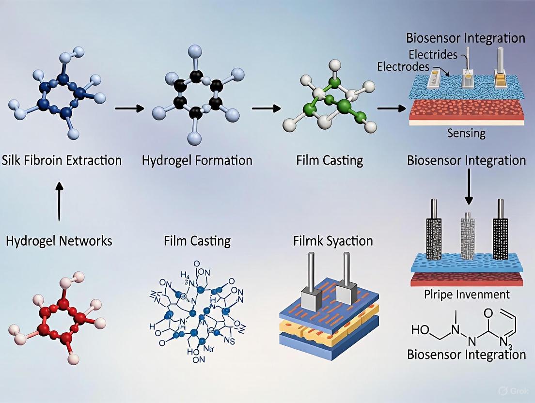
The following diagram illustrates the complete workflow from silkworm cocoon to a finished functional hydrogel.
Quantitative Performance of SF-Based Hydrogels in Sensing
Advanced SF composite hydrogels have been engineered to meet the demanding requirements of high-performance wearable sensors. These materials often combine SF with other polymers to create synergistic networks with enhanced properties.
Table 3: Performance Metrics of Advanced SF-Based Hydrogel Sensors
| Hydrogel Composition | Key Additives/Features | Mechanical & Electrical Performance | Sensing Application |
|---|---|---|---|
| SF/Poly-acrylic acid [9] | TA-Fe₃O₄@MXene catalytic system; biomimetic micro-architecture. | Stretchability: 946%; Sensitivity (Gauge Factor): 4.05; Stable for >100 cycles. | Wearable sensor for physiological signals. |
| SF/Polyacrylamide/Methyl Cellulose [4] | Triple-network; pH-pre-regulated precursor. | Hysteresis: 7.2%; Conductivity: 0.57 S/m; Elastic Modulus: 58.9 kPa. | Multi-channel wireless human motion, ECG, and EMG detection. |
| SF/Magnetic Nanoparticles [10] | Iron oxide nanoparticles (IONPs) for magnetic response. | Enables remote-controlled drug release under external magnetic field. | Intelligent drug delivery system. |
Experimental Protocol: Fabrication of a Photo-Cross-Linked SF-Sericin Hydrogel for pH Visualization
This protocol details the synthesis of a double-network SF-Sericin hydrogel integrated with a natural pH indicator, suitable for creating visual biosensor strips [8].
Research Reagent Solutions
Table 4: Essential Reagents for SF-Sericin Hydrogel Fabrication
| Item | Function/Description |
|---|---|
| Bombyx mori Cocoons | Raw source material for silk fibroin and sericin. |
| Sodium Carbonate (Na₂CO₃) | Degumming agent for separating sericin from fibroin. |
| Riboflavin (Vitamin B₂) | Biocompatible photoinitiator for UV cross-linking. |
| Natural Anthocyanins | pH-responsive dye extracted from red cabbage; enables visual colorimetry. |
| Lithium Bromide (LiBr) | Electrolyte salt used to dissolve silk fibroin. |
Step-by-Step Procedure
Solution Preparation (Day 1):
- Degumming and Co-extraction: In a 500 mL beaker, add 5.0 g of chopped silk cocoons to 250 mL of 0.02 M sodium carbonate solution. Boil for 30-60 minutes with constant stirring. Control the degumming time precisely to tune the final sericin content in the mixed solution.
- Purification: After cooling, rinse the degummed fibroin fibers thoroughly with copious amounts of ultrapure water (3 x 500 mL) to remove all traces of sericin and carbonate. Gently squeeze out excess water.
- Dissolution: Dissolve the washed, wet fibroin fibers in 25 mL of 9.3 M lithium bromide solution at 60°C for 1-2 hours until fully dissolved.
- Dialysis: Load the solution into a dialysis tube (MWCO 12-14 kDa) and dialyze against ultrapure water for 48 hours, changing the water every 6-8 hours, to remove the LiBr salt.
- Centrifugation & Concentration: Centrifuge the purified aqueous SF solution at 9,000 rpm for 20 minutes to remove impurities and aggregates. Decant the clear supernatant and concentrate it to a final concentration of 8-10% (w/v) using a centrifugal evaporator or by air-drying at 4°C.
Hydrogel Fabrication (Day 3):
- Mixing: To 5 mL of the concentrated SF-Serici mixed solution, add 100 µL of a 10 mM Riboflavin (RB) solution and 200 µL of anthocyanin extract (Cy). Mix the solution thoroughly by gentle vortexing for 2 minutes. Protect from light using aluminum foil.
- Photo-Cross-linking: Pipette the mixture into a polydimethylsiloxane (PDMS) mold. Expose the mold to UV light (wavelength 365 nm, intensity 10 mW/cm²) for 15 minutes to initiate cross-linking and form the SF-Seri/RB@Cy hydrogel.
- Post-processing: Carefully demold the resulting hydrogel and store it in phosphate-buffered saline (PBS) at 4°C until use.
The logical workflow and responsive mechanism of the resulting smart hydrogel are summarized in the diagram below.
Application in Biosensor Strips: Mechanisms and Workflow
The integration of SF hydrogels into biosensor strips leverages their tunable mechanical properties, biocompatibility, and capacity for functionalization with conductive elements or molecular probes [9] [4]. For instance, a SF-based hydrogel can serve as both the sensing interface and the matrix for immobilizing recognition elements (e.g., enzymes, antibodies).
A typical biosensor fabrication workflow involves casting the prepared SF hydrogel solution onto a flexible substrate (e.g., polyester film), patterning it into a strip, and functionalizing it with specific receptors. When the strip encounters the target analyte (e.g., glucose, specific ions, or biomarkers), a change in the hydrogel's properties occurs—such as swelling, a shift in conductivity, or a colorimetric response—which is transduced into a measurable electrical or optical signal [9] [8]. The high water content and porous structure of the hydrogel facilitate rapid analyte diffusion, leading to faster response times.
Silk fibroin (SF), a natural protein derived from Bombyx mori silkworm cocoons, has emerged as a premier biomaterial for fabricating advanced hydrogel film biosensor strips. Its unique combination of properties allows for the creation of devices that are not only highly functional but also compatible with biological systems. For researchers and drug development professionals, understanding and controlling these key physicochemical properties—biocompatibility, biodegradability, and mechanical robustness—is fundamental to developing reliable and effective biosensing platforms. This document details the core principles, quantitative relationships, and standardized protocols for optimizing these properties specifically for biosensor applications, providing a scientific framework for innovative research and development.
Fundamental Properties of Silk Fibroin Hydrogels
Molecular Basis of Key Properties
The exceptional properties of silk fibroin stem from its unique molecular architecture. The protein consists of a heavy chain (~390 kDa) and a light chain (~26 kDa) linked by a single disulfide bond [2] [11]. The heavy chain contains 12 hydrophobic repetitive domains rich in glycine (∼45%), alanine (∼30%), and serine (∼12%), which are interspersed with 11 hydrophilic non-repetitive domains [2]. The hydrophobic domains, particularly those with the GAGAGS peptide sequence, self-assemble into crystalline β-sheets that act as physical cross-links [12] [11]. This structure results in a natural block copolymer that provides mechanical strength through the β-sheet crystals, while the amorphous regions contribute to elasticity and toughness [11]. This hierarchical structure is the foundation for the tunable properties of SF hydrogels.
The table below summarizes the key physicochemical properties of silk fibroin hydrogels relevant to biosensor fabrication.
Table 1: Key Physicochemical Properties of Silk Fibroin Hydrogels for Biosensing
| Property | Molecular & Structural Basis | Typical Range/Value | Tunability Factors |
|---|---|---|---|
| Biocompatibility | Purification via degumming to remove immunogenic sericin; natural protein structure [2] [13]. | Low immunogenicity; supports cell adhesion & proliferation [2] [12]. | Sericin removal efficiency [2]; cross-linking method (chemical residues can cause cytotoxicity) [14]. |
| Biodegradability | Enzymatic hydrolysis by proteases (e.g., protease XIV, α-chymotrypsin) cleaving protein backbone into amino acids [2] [12]. | Days to years, depending on β-sheet content and cross-linking density [2] [13]. | β-sheet content (higher content slows degradation) [2] [12]; cross-linking density [12]. |
| Mechanical Robustness | β-sheet crystallites acting as physical cross-links; nanofibrillar network [2] [11]. | Young's Modulus: ~0.01-0.1 MPa (conventional) up to 6.5 ± 0.2 MPa (high-strength formulations) [15]. | Protein concentration [15]; cross-linking method & density [14]; secondary structure content [12]. |
Experimental Protocols for Characterization
Protocol: Assessing In Vitro Biodegradation
This protocol determines the degradation profile of SF hydrogel films, which is critical for predicting biosensor functional lifetime.
Research Reagent Solutions & Materials:
- Silk Fibroin Hydrogel Film: Sample of known dimensions and mass.
- Protease XIV Solution: 1.0 U/mL protease XIV in 0.1 M phosphate-buffered saline (PBS), pH 7.4 [2].
- Control PBS: 0.1 M PBS, pH 7.4, without enzymes.
- Water Bath: Maintained at 37°C.
- Analytical Balance.
Procedure:
- Initial Mass (W₀): Pre-weigh the dry SF hydrogel film sample accurately using an analytical balance.
- Incubation: Place the sample in a vial containing 10 mL of the pre-warmed Protease XIV Solution. For a negative control, incubate a separate sample in 10 mL of Control PBS.
- Agitation & Sampling: Place vials in the 37°C water bath with constant, gentle agitation. At predetermined time intervals (e.g., daily for the first week, then weekly), remove the sample from the enzymatic solution.
- Rinsing & Drying: Rinse the sample thoroughly with deionized water to halt enzymatic activity and remove salts.
- Dry Mass Measurement (Wₐ): Lyophilize or dry the sample to a constant weight and record the dry mass.
- Calculation: Calculate the remaining mass percentage at each time point: Remaining Mass (%) = (Wₐ / W₀) × 100.
- Data Analysis: Plot Remaining Mass (%) versus time to generate a degradation profile. The half-life of the film can be extrapolated from this curve.
Protocol: Determining Mechanical Properties via Uniaxial Compression
This protocol characterizes the mechanical robustness, specifically the compressive modulus, of SF hydrogel films.
Research Reagent Solutions & Materials:
- Hydrated SF Hydrogel Film: Cut into a standardized cylinder (e.g., 10 mm diameter, 5 mm height).
- Universal Mechanical Testing System equipped with a calibrated load cell and parallel plate geometry.
- PBS Buffer: To keep the sample hydrated during testing.
Procedure:
- Hydration: Equilibrate the SF hydrogel sample in PBS for at least 24 hours before testing to ensure full hydration.
- Mounting: Carefully center the hydrated sample on the lower plate of the testing system. Bring the upper plate into light contact with the sample surface to define zero position and preload.
- Compression Test: Compress the sample at a constant strain rate (e.g., 1 mm/min) until a predetermined strain (e.g., 60%) or failure is reached.
- Data Collection: Record the force and displacement data throughout the test.
- Analysis: Convert force-displacement data to a stress-strain curve.
- Stress (σ) = Force (F) / Original Cross-sectional Area (A₀)
- Strain (ε) = Change in height (ΔH) / Original height (H₀)
- Modulus Calculation: The Compressive Modulus (Young's Modulus) is determined from the slope of the initial linear region of the stress-strain curve (typically between 10-20% strain) [15].
Property Interrelationships and Biosensor Design
The three core properties are not independent; they are intrinsically linked through the underlying structure of the SF hydrogel. The following diagram illustrates the strategic balance between β-sheet content and these key properties, which is central to biosensor design.
Diagram 1: Property balance for biosensor design.
The Scientist's Toolkit: Cross-Linking Methods for Tunable Properties
The method used to induce gelation and form the SF hydrogel network is a critical design choice that directly impacts all key properties. The table below compares common techniques.
Table 2: Cross-Linking Methods for Silk Fibroin Hydrogels
| Method | Mechanism | Advantages | Disadvantages for Biosensing |
|---|---|---|---|
| Physical (e.g., Sonication, Shear) [14] | Induction of β-sheet formation via energy input (ultrasound, vortex) [14]. | Rapid; no chemical cross-linkers, high biocompatibility [14]. | Can be difficult to control uniformly; may produce weaker gels. |
| Chemical (e.g., Genipin) [14] | Covalent bonds between amino acid side chains. | Rapid gelation; stable, strong networks [12] [14]. | Potential cytotoxicity from residual cross-linkers [12] [14]. |
| Enzymatic (e.g., HRP) [8] [14] | Enzyme-mediated (e.g., Horseradish Peroxidase) radical coupling. | Highly biocompatible; mild reaction conditions; elastic gels [8] [14]. | Can be time-consuming; cost of enzymes [12]. |
| Photo-Crosslinking [8] [14] | Radical polymerization initiated by light and a photo-initiator (e.g., Riboflavin). | Rapid; excellent spatiotemporal control; efficient [8] [12]. | Potential cytotoxicity of photo-initiators (mitigated by using biocompatible ones like Riboflavin) [8] [12]. |
Advanced Functionalization for Biosensing
Moving beyond the base material, functionalization is key to creating a responsive biosensor. A core-shell architecture is a advanced strategy to decouple mechanical requirements from biosensing functions. The diagram below outlines the workflow for creating such a functionalized biosensor strip.
Diagram 2: Biosensor strip fabrication workflow.
Protocol: Fabrication of a Core-Shell SF Hydrogel Biosensor Strip
This protocol leverages a core-shell design to integrate mechanical robustness with high-sensitivity biosensing [16].
Research Reagent Solutions & Materials:
- Purified SF Solution: ≥15% w/v for core; ~4-6% w/v for shell [16].
- Functional Fusion Protein: e.g., BC-MAP (B and C domains of Protein A fused to a Mussel Adhesive Protein) [16].
- Photo-initiator: Riboflavin (Vitamin B2) solution [8].
- Antibody Solution: The specific immunoglobulin for the target analyte.
- UV Light Source: ~365-470 nm wavelength.
- Polydimethylsiloxane (PDMS) Mold: With micro-scale features for the biosensor strip.
Procedure:
- Core Hydrogel Precursor: Mix high-concentration SF solution (≥15% w/v) with Riboflavin photo-initiator.
- Core Molding & Cross-linking: Pour the core precursor into a PDMS mold. Expose to visible/UV light to form a physically robust, cross-linked core hydrogel.
- Shell Hydrogel Precursor: Mix lower-concentration SF solution (~4-6% w/v) with the BC-MAP fusion protein and Riboflavin.
- Shell Application & Bonding: Apply the shell precursor over the core structure. A second, brief photo-cross-linking step forms the shell and covalently bonds it to the core via di-tyrosine coupling facilitated by the MAP domain [16].
- Antibody Immobilization: Incubate the core-shell hydrogel strip in a solution of the specific antibody. The BC domains in the shell will immobilize the antibodies via high-affinity binding [16].
- Biosensor Operation: Upon exposure to the sample containing the target analyte, the analyte binds to the immobilized antibody, leading to a measurable signal (e.g., optical, electrochemical).
This structured approach to understanding, characterizing, and functionalizing silk fibroin hydrogels provides a solid foundation for developing the next generation of sophisticated and reliable biosensor strips.
Silk fibroin hydrogels have garnered significant interest in the biomedical field, particularly for advanced applications such as biosensor strip fabrication, due to their remarkable biocompatibility, tunable mechanical properties, and biodegradability [2]. The core process that transforms aqueous silk fibroin solutions into solid-like hydrogels is gelation, a phase transition critically governed by the formation of β-sheet structures and various cross-linking mechanisms [7] [2]. For biosensor films, precisely controlling this process is paramount, as it directly determines the film's mechanical integrity, porosity, and stability in aqueous environments. This document details the underlying gelation mechanisms and provides standardized protocols for fabricating silk fibroin hydrogels with properties tailored for biosensing applications, providing a vital resource for researchers and drug development professionals.
Gelation Mechanisms and Cross-linking Strategies
The gelation of silk fibroin can be initiated through physical, chemical, or enzymatic means, all of which ultimately promote the conformational transition of the protein chains from random coils or silk I structures to insoluble β-sheet crystallites [2] [17]. These β-sheet domains act as physical cross-links, anchoring the three-dimensional network of the hydrogel.
Table 1: Primary Gelation Mechanisms for Silk Fibroin Hydrogels
| Mechanism Type | Key Features | Impact on β-Sheet Formation | Advantages for Biosensors |
|---|---|---|---|
| Physical Cross-linking (e.g., Sonication, Solvent Exchange, CO₂ Treatment) | Relies on non-covalent interactions; often initiated by altering pH, temperature, or ionic strength [2] [17]. | Induces self-assembly of hydrophobic domains into β-sheet crystallites that act as physical cross-links [2]. | High biocompatibility; avoids chemical residues; process can be mild and controllable [8]. |
| Chemical Cross-linking (e.g., Genipin, Glutaraldehyde) | Uses cross-linking agents to form covalent bonds between amino acid side chains (e.g., primary amines) [17]. | Can be designed to occur before or after β-sheet formation, significantly affecting final mechanics and morphology [17]. | Enhances mechanical strength and stability; allows for precise tuning of cross-link density [17]. |
| Photo-Cross-linking (e.g., Riboflavin) | A specific chemical method using a photo-initiator (e.g., Riboflavin) and light exposure to create covalent bonds [8] [18]. | The cross-linked network can template subsequent β-sheet formation, leading to a dual-network hydrogel [8]. | Enables spatial and temporal control; rapid gelation (e.g., ≤15 min); suitable for patterning sensor strips [8] [18]. |
| Enzymatic Cross-linking (e.g., Horseradish Peroxidase) | Uses enzymes to catalyze the formation of covalent bonds between tyrosine residues [8]. | Compatible with β-sheet formation; can be performed under physiological conditions. | High biocompatibility; gelation rate can be programmed [8]. |
The Role of β-Sheet Crystallites
The fundamental structural units of silk fibroin are β-sheet crystallites, primarily formed by the hydrophobic domains of the heavy fibroin chains rich in glycine, alanine, and serine repeats [2]. During gelation, these regions self-assemble through intermolecular and intramolecular interactions, including hydrogen bonding and hydrophobic effects, creating stable, water-insoluble nodes within the hydrogel network [2] [17]. The content and size of these β-sheet domains are the primary determinants of the hydrogel's mechanical properties, degradation rate, and swelling behavior. A higher degree of β-sheet crystallinity generally results in stiffer and more stable hydrogels but may also increase brittleness [2] [17].
Synergistic and Dual-Network Strategies
Advanced hydrogel designs for biosensors often employ synergistic or dual-network strategies to overcome the limitations of single-mechanism systems. A prominent example is the silk fibroin-sericin dual-network hydrogel. In this system, sericin, a hydrophilic protein naturally cocooned with fibroin, is incorporated to form a second network. Sericin's random coil structure and hydrophilic groups significantly improve the hydrogel's toughness and elasticity, mitigating the brittleness often associated with high β-sheet content fibroin networks [8] [18]. Furthermore, the chronology of cross-linking events can be engineered for precise property tuning. As demonstrated in [17], performing genipin-mediated chemical cross-linking after high-pressure CO₂-induced β-sheet gelation anchors the amorphous regions of the protein chains, resulting in a stiffer hydrogel compared to chemical cross-linking before gelation.
Quantitative Data on Hydrogel Properties
The properties of silk fibroin hydrogels can be finely tuned by varying the fabrication parameters, as illustrated by the following quantitative data extracted from recent studies.
Table 2: Tunable Properties of Silk Fibroin-Based Hydrogels
| Hydrogel System | Gelation Time | Maximum Stress / Young's Modulus | Strain at Break / Swelling | Key Tuning Parameter |
|---|---|---|---|---|
| SF-Seri/RB Dual-Network [8] [18] | ≤ 15 minutes | 54 kPa (Stress) | 168% (Strain) | Sericin content; higher content accelerates gelation and improves toughness. |
| SH/SS Blend Hydrogel (Sulfhydrylated HA/SF) [19] | 0.4 to 32 hours | 1.2 - 10.9 kPa (Young's) | N/A | SH/SS mass ratio; higher SS content increases modulus and degradation resistance. |
| Genipin-Cross-linked SF [17] | N/A | Stiffness highly tunable | N/A | Order of cross-linking; Genipin after β-sheet formation yields a stiffer gel. |
| PVA/GL Dual-Network (Illustrative Composite) [20] | N/A | Tensile strength increased 3.18x | N/A | Glycerol (GL) content (50% optimal for strength). |
Detailed Experimental Protocols
Protocol 1: Fabrication of a Photo-Cross-linked SF-Seri Dual-Network Hydrogel for pH-Visual Sensing
This protocol is adapted from [8] [18] and is highly relevant for creating biosensor strips with a visual readout, such as for urine pH monitoring.
4.1.1 Research Reagent Solutions
Table 3: Essential Materials for Photo-Cross-linked SF-Seri Hydrogel
| Reagent/Material | Function/Description |
|---|---|
| Bombyx mori Cocoons | Source of native silk proteins (fibroin and sericin). |
| Sodium Carbonate (Na₂CO₃) | Degumming agent for the controlled removal of sericin. |
| Riboflavin (RB) | Biocompatible photo-initiator; cross-links under visible light. |
| Natural Anthocyanin (Cy) | pH-responsive dye; extracted from red cabbage for visual color change. |
4.1.2 Step-by-Step Procedure
One-Step SF-Seri Mixed Solution Preparation:
- Degum Bombyx mori cocoons in a sodium carbonate solution (concentration and time are critical tuning parameters).
- Precisely control the degumming process to achieve a tunable sericin retention, resulting in an aqueous SF-Seri mixed solution without the need for separate extraction and purification [8] [18].
Precursor Solution Preparation:
- Adjust the concentration of the SF-Seri solution to the desired level (e.g., 10 wt% fibroin).
- Add Riboflavin (RB) to the solution. An RB concentration of at least 1 mM is typically required for effective cross-linking [18].
- Incorporate natural anthocyanin (Cy) extract, optimizing the loading process for a clear and distinct colorimetric response to pH changes.
- Systematically optimize parameters including sericin content, precursor solution pH, and RB concentration.
Photo-Induced Gelation:
- Pipette the precursor solution into the desired mold (e.g., a biosensor strip format).
- Expose the solution to visible light irradiation. Under optimized conditions, gelation can occur within 15 minutes [8].
- Control the irradiation time to fine-tune the cross-linking density and the resulting hydrogel's mechanical properties and swelling ratio.
Protocol 2: Tunable Gelation via Combined Physical and Chemical Cross-linking
This protocol, based on [17], highlights how the sequence of cross-linking events can be used to precisely control the viscoelastic properties of the final hydrogel, which is crucial for the mechanical flexibility of biosensor strips.
4.2.1 Research Reagent Solutions
Table 4: Essential Materials for Genipin-Tuned SF Hydrogel
| Reagent/Material | Function/Description |
|---|---|
| Degummed Silk Fibroin Fibers | The primary structural protein polymer. |
| Lithium Bromide (LiBr) | Solvent for dissolving silk fibroin fibers. |
| Genipin | Biocompatible chemical cross-linker that reacts with primary amines. |
| High-Pressure CO₂ Reactor | Equipment for controlled physical gelation via pH reduction. |
4.2.2 Step-by-Step Procedure
Silk Fibroin Solution Preparation:
- Degum silk cocoons twice in Na₂CO₃ solution (e.g., 1.1 and 0.4 g/L) at 98°C to remove sericin completely [17].
- Dissolve the degummed silk fibroin fibers in 9.3 M LiBr at 65°C.
- Dialyze the solution against deionized water using a Slide-A-Lyzer cassette (3.5K MWCO) to remove the salt.
- Determine the protein concentration via spectrophotometry and adjust to the working concentration (e.g., 3-4% w/v).
Cross-linking Chronology Strategy:
- Path A: Chemical Cross-linking BEFORE Physical Gelation
- Add Genipin (e.g., 1 mM final concentration) to the fibroin solution and allow it to react. This increases the molecular weight of the protein in solution.
- Subsequently, induce physical gelation via high-pressure CO₂ treatment (e.g., 60 bar) to form β-sheet crystals. This pathway results in a hydrogel with altered gel morphology and a decreased stiffness response [17].
- Path B: Chemical Cross-linking AFTER Physical Gelation
- First, induce physical gelation by subjecting the pure fibroin solution to high-pressure CO₂ treatment to form the β-sheet network.
- Then, immerse the pre-formed physical hydrogel in a Genipin solution to covalently anchor the amorphous regions of the protein chains. This pathway yields a hydrogel with significantly increased stiffness [17].
- Path A: Chemical Cross-linking BEFORE Physical Gelation
Application in Biosensor Strip Fabrication: Concluding Remarks
The controlled formation of β-sheets and the strategic application of cross-linking methods are the cornerstones of engineering functional silk fibroin hydrogel films for biosensing. The protocols outlined herein provide a framework for fabricating hydrogels with bespoke mechanical properties, gelation kinetics, and integrated smart functions, such as visual pH response. The SF-Seri/RB dual-network system is particularly promising for disposable diagnostic strips due to its rapid gelation, robust mechanics, and ease of functionalization. For ongoing research, focusing on the long-term stability of these hydrogels in various biological fluids, the reproducibility of large-scale manufacturing, and the integration of additional sensing modalities (e.g., electrochemical detection) will be critical steps toward translating silk fibroin hydrogel biosensors from the laboratory to clinical and commercial applications.
Inherent Advantages over Collagen and Synthetic Polymers for Biosensing
Silk fibroin (SF), a natural protein polymer derived from Bombyx mori silkworm cocoons, has evolved from its traditional textile applications to become a leading material in the biomedical field. Its unique combination of remarkable mechanical properties, excellent biocompatibility, and flexible processability positions it as a superior alternative to both natural polymers like collagen and synthetic polymers for advanced biosensing applications [21] [2]. In the context of biosensor development, particularly for hydrogel film strip fabrication, SF's tunable molecular structure and abundant functional groups enable the creation of highly sensitive, stable, and adaptable sensing platforms that outperform conventional materials.
SF's structural backbone, comprised of hydrophobic repetitive domains rich in glycine, alanine, and serine that form stable β-sheet crystallites, and hydrophilic non-repetitive domains, is the origin of its exceptional material properties [2]. This hierarchical structure can be precisely engineered through various processing methods to yield hydrogels, films, and other morphologies ideal for biosensor fabrication. Unlike many synthetic polymers, SF is sustainable, biodegradable, and offers a robust clinical heritage through its long-standing use as an FDA-approved suture material [21]. For researchers and drug development professionals, these attributes translate into reliable, high-performance biosensing platforms capable of everything from point-of-care diagnostics to continuous physiological monitoring.
Comparative Material Advantages
The selection of a substrate material is fundamental to biosensor performance, influencing everything from signal transduction and bioreceptor immobilization to biocompatibility and operational lifetime. Silk fibroin presents a compelling set of advantages when directly compared to two widely used material categories: the natural polymer collagen and various synthetic polymers.
Table 1: Quantitative Comparison of Biosensing Substrate Materials
| Property | Silk Fibroin (SF) | Collagen | Synthetic Polymers (e.g., PDMS, PANI) |
|---|---|---|---|
| Tensile Strength | High (up to 600 MPa in native fiber) [2] | Low (weak, gels easily) | Variable (PDMS: very low; PANI: moderate) [22] |
| Young's Modulus | Tunable, high toughness (70 MJ m⁻³) [2] | Low, soft | Variable |
| Biodegradability | Controllable (days to months) [21] [2] | Rapid, uncontrollable | Typically non-biodegradable [22] |
| Biocompatibility | Excellent, immunologically inert [2] | Good, but can elicit immune response | Varies, often poor (inflammatory responses) [22] |
| Structural Stability in Aqueous Environments | High (can be enhanced via oriented crystallization) [23] | Low (swells, mechanically weak) | Hydrophobic or unstable swelling |
| Processability & Functionalization | High (abundant -OH, -COOH groups for modification) [8] [2] | Moderate | Low to Moderate (often requires complex surface treatments) [22] |
| Optical Properties | Optically transparent, suitable for imaging [21] | Transparent | Often opaque |
| Cost & Source | Abundant, low-cost source [2] | High-cost, mammalian extraction | Low-cost, petroleum-based |
Advantages over Collagen
- Superior Mechanical Robustness: SF's mechanical strength and toughness far exceed those of collagen, which is typically weak and forms soft gels. This inherent strength allows for the fabrication of durable, freestanding biosensor strips that can withstand handling and operational stresses without deformation or failure [2]. This is a critical advantage for wearable or implantable sensor designs.
- Tunable and Predictable Degradation: A significant limitation of collagen is its rapid and relatively uncontrollable degradation profile. In contrast, the degradation rate of SF can be precisely engineered from days to months by modulating the crystalline β-sheet content during processing [21] [2]. This tunability ensures that the biosensor platform remains structurally intact for the required duration of its application, preventing premature functional failure.
- Enhanced Aqueous Stability: SF-based materials, particularly those engineered with oriented crystallization (OC), demonstrate remarkable stability in aqueous and in vivo environments, resisting the rapid swelling and structural disintegration that can plague collagen-based sensors [23]. This property is paramount for maintaining the integrity of the imprinted sensing cavities and conductive pathways in hydrogel film strips during operation.
Advantages over Synthetic Polymers
- Exceptional Biocompatibility and Biointegration: Unlike synthetic polymers like poly(dimethylsiloxane) (PDMS) or polyaniline (PANI), which can provoke inflammatory responses and fibrotic encapsulation, SF is highly biocompatible and immunologically inert [2] [22]. This promotes seamless integration with biological tissues, minimizes the foreign body response, and ensures accurate signal acquisition in vivo by reducing biofouling.
- Sustainable and Biodegradable Platform: SF is a natural, biodegradable polymer, addressing growing concerns about electronic waste and environmental sustainability associated with non-biodegradable synthetic polymers [22]. Its production from renewable resources aligns with green chemistry principles and is a key advantage for developing next-generation, environmentally responsible diagnostic devices.
- Facile Functionalization and ECM-Mimicry: SF's molecular structure presents abundant functional groups (e.g., hydroxyl, carboxyl) that facilitate straightforward chemical modification and covalent immobilization of biorecognition elements (e.g., antibodies, enzymes) [8] [2]. Furthermore, SF hydrogels can be engineered to closely mimic the biochemical and mechanical properties of the native extracellular matrix (ECM), providing a more physiologically relevant microenvironment for cell-based sensing than most synthetic substrates [21].
Application Notes for Biosensor Fabrication
SF Hydrogel Film Strip for Electrochemical Detection
The integration of SF hydrogel films with electrochemical transducers creates a powerful platform for label-free biosensing. Molecularly Imprinted Polymer (MIP) composites can be incorporated into the SF matrix to create highly selective recognition sites for specific analytes.
Table 2: Performance Metrics of a Representative SF-Based MIP Biosensor for Collagen Peptides
| Parameter | Performance Value |
|---|---|
| Detection Principle | Electrochemical (Current Response) |
| Target Analyte | Collagen Peptides |
| Linear Detection Range | 0.1 – 1000 µg/mL [24] |
| Limit of Detection (LOD) | 1.01 µg/mL [24] |
| Limit of Quantification (LOQ) | 4.46 µg/mL [24] |
| Sensitivity | 8.38 (Current vs. Concentration) [24] |
| Correlation Coefficient (R²) | 0.9436 [24] |
A key application is the detection of collagen peptides, which are critical biomarkers for degenerative musculoskeletal diseases [24]. An SF-MIP composite sensor demonstrated a wide detection range and high sensitivity, offering a rapid and cost-effective alternative to traditional methods like ELISA or HPLC.
Smartphone-Integrated Optical SF Biosensor
SF's optical transparency and capacity for functionalization make it an excellent material for optical biosensors that can be integrated with smartphone-based detection systems. These systems leverage the smartphone's camera as a detector and its processor for data analysis, enabling powerful point-of-care diagnostics [25].
A notable example is a pH-visualized SF-sericin composite hydrogel for urinary health monitoring [8]. This system uses natural anthocyanin extracted from red cabbage as a pH-responsive dye incorporated into the SF hydrogel. Upon contact with urine, the hydrogel displays distinct color changes corresponding to pH levels: green for the normal range, and reddish-purple or blue for abnormal acidity or alkalinity, serving as a visual warning [8]. This platform demonstrates excellent mechanical properties (maximum stress of 54 kPa, strain of 168%) and high water absorption (566%), making it ideal for integration into wearable products like smart diapers for vulnerable populations [8].
Experimental Protocols
Protocol: Fabrication of a Basic Silk Fibroin Hydrogel Film
This protocol details the foundational process for creating a stable, free-standing SF hydrogel film, which can serve as a substrate for various biosensing applications [2] [23].
Objective: To prepare a pure, biocompatible SF hydrogel film with tunable mechanical properties and degradation kinetics.
The Scientist's Toolkit: Research Reagent Solutions
| Reagent/Material | Function/Note | Supplier Example |
|---|---|---|
| Bombyx mori Cocoons | Raw source of Silk Fibroin | Commercial supplier |
| Sodium Carbonate (Na₂CO₃) | Degumming agent to remove sericin | Sigma-Aldrich |
| Lithium Bromide (LiBr) | Chaotropic salt for dissolving degummed SF | Sigma-Aldrich |
| Slide-A-Lyzer Dialysis Cassettes (MWCO 3,500) | Removal of salts and small impurities | Pierce, Thermo Fisher |
| Riboflavin (Vitamin B₂) | Biocompatible photo-initiator for cross-linking | Sigma-Aldrich |
| Deionized Water | Solvent for all aqueous steps | N/A |
Step-by-Step Procedure:
- Degumming: Boil 5 grams of Bombyx mori cocoons in 2 liters of 0.02 M sodium carbonate (Na₂CO₃) solution for 30 minutes to dissolve and remove the sericin gum. Rinse the resulting SF fibers thoroughly with copious amounts of deionized water and air-dry for 12 hours [2] [23].
- Dissolution: Dissolve the degummed SF fibers in a 9.3 M lithium bromide (LiBr) solution at 60°C for 4 hours with continuous stirring to achieve a complete dissolution of the SF protein [23].
- Dialysis: Transfer the SF/LiBr solution into a dialysis cassette (MWCO 3,500) and dialyze against deionized water for 48 hours to remove the LiBr salt. Change the water frequently. The solution will become slightly opaque during this process.
- Concentration & Purification: Centrifuge the dialyzed SF solution at 9,000 rpm for 20 minutes at 4°C to remove any aggregates and impurities. Collect the supernatant, which is the purified aqueous SF solution. The concentration can be determined by weighing the solid residue after drying a known volume and is typically adjusted to 6-8% (w/v) for film casting.
- Film Casting & Cross-linking: Pour the SF solution into a polystyrene Petri dish. For photo-cross-linking, add 0.1% (w/v) riboflavin to the solution and expose to visible light for 15-30 minutes to induce gelation and stabilize the hydrogel network [8]. Alternatively, physical cross-linking can be induced by leaving the cast solution in a fume hood for 24-48 hours, which promotes β-sheet formation.
- Post-processing: Once gelled, the SF hydrogel film can be carefully peeled from the mold. It may be further treated with methanol or autoclaving to increase β-sheet content and thus, mechanical strength and stability.
Protocol: Fabrication of an SF-Based MIP Electrochemical Biosensor Strip
This protocol builds upon the basic SF film fabrication to create a specific, sensitive biosensor for a target analyte, such as collagen peptides [24].
Objective: To fabricate a screen-printed electrode (SPE) modified with an SF-MIP composite for the electrochemical detection of collagen peptides.
Step-by-Step Procedure:
- Prepare Pre-polymer Mixture: In a microtube, combine the following to form a homogeneous pre-polymer solution:
- Monomer: Hydroxyproline and an amino acid standard (e.g., AAS18 from Sigma-Aldrich).
- Initiator: Azobisisobutyronitrile (AIBN), 1.5 mg (5 mg/mL).
- Cross-linker: N,N′-(1,2-dihydroxyethylene)bisacrylamide (DHEBA), 47 mg.
- Auxiliary Cross-linker: Glutaraldehyde (GA), 9.4 µL.
- Solvent: Dimethyl sulfoxide (DMSO), 300 µL.
- Heat the mixture at 80°C for 30 minutes with stirring, then cool to room temperature [24].
- Modify the Working Electrode: Deposit a precise volume (e.g., 5 µL) of the pre-polymer solution onto the carbon working electrode surface of a commercial SPE, ensuring complete coverage.
- Template Imprinting: Add 1-2 µL of the target template (e.g., 1 mg/mL collagen peptide solution) onto the coated electrode.
- Polymerization: Place the modified SPE in a UVA chamber and expose to 365 nm wavelength light for 3 hours to complete the polymerization process and "lock in" the molecular imprints [24].
- Template Removal: Wash the polymerized SF-MIP/SPE thoroughly with a suitable buffer (e.g., Phosphate Buffered Saline, PBS) and a mild detergent solution to remove the embedded collagen peptide templates, thereby creating the specific recognition cavities.
- Sensor Validation: Characterize the sensor using electrochemical techniques such as Electrochemical Impedance Spectroscopy (EIS) or amperometry by measuring the current response across a range of collagen peptide concentrations (e.g., 0.1–1000 µg/mL) to establish a calibration curve [24].
Visualization of the SF Biosensing Mechanism
The high performance of SF-based biosensors stems from the synergistic relationship between its material properties and the integrated sensing mechanism, as illustrated below.
From Solution to Sensor: Fabrication Techniques and Functional Applications
Regenerated silk fibroin (RSF) has emerged as a premier biomaterial for fabricating advanced biosensing platforms, such as hydrogel film-based biosensor strips, due to its exceptional biocompatibility, tunable mechanical properties, and excellent optical clarity [26] [27]. The performance of these biosensors is intrinsically linked to the molecular weight, structural integrity, and purity of the underlying RSF. This application note details a standardized workflow for the preparation of high-quality RSF, with a specific focus on methodologies that enhance the material's properties for biosensing applications. The protocols herein are designed to provide researchers with reliable and reproducible techniques to obtain RSF that forms robust, stable, and sensitive hydrogel films.
The journey from raw silk cocoons to a pure regenerated silk fibroin solution suitable for hydrogel film biosensors involves three critical stages: degumming, dissolution, and purification. The following diagram illustrates the complete workflow, highlighting key steps and decision points.
Detailed Protocols and Data Comparison
Degumming: Sericin Removal
The primary objective of degumming is to remove the sericin gum that binds silk filaments, which can cause immunogenic responses in biomedical applications [28]. The choice of degumming method significantly impacts the molecular weight and integrity of the final fibroin.
Protocol 1: Traditional Alkaline Degumming with Na₂CO₃ [29] [30]
- Procedure: Boil 5 g of raw silk cocoons in 500 mL of 0.02 M sodium carbonate (Na₂CO₃) solution for 30 minutes under constant stirring.
- Rinsing: Thoroughly rinse the degummed silk fibers with copious amounts of ultrapure water (≥ 5 times) to remove residual sericin and alkali.
- Drying: Air-dry the cleaned fibers overnight at room temperature.
- Output: The mass loss should be approximately 25-30%, corresponding to the sericin content. A higher mass loss (e.g., >30%) may indicate fibroin degradation.
Protocol 2: Rapid Microwave-Assisted Degumming [29]
- Reagent Preparation: Prepare a solution containing an anionic detergent like sodium dodecyl sulfate (SDS).
- Procedure: Submerge raw silk in the SDS solution and subject it to repeated short-term cycles of microwave irradiation.
- Rinsing and Drying: As in Protocol 1, rinse thoroughly with ultrapure water and air-dry.
- Output: This gentler method yields a mass loss of ~32.8% and, crucially, preserves high-molecular-weight fibroin chains (evidenced by a distinct band at 350 kDa on SDS-PAGE), unlike the standard method which shows degradation.
Table 1: Comparison of Silk Fibroin Degumming Methods
| Method | Key Reagents | Conditions | Processing Time | Impact on SF | Key Outcome |
|---|---|---|---|---|---|
| Traditional Alkaline [29] [30] | 0.02 M Na₂CO₃ | 100°C, 30-60 min | ~1-2 hours | Higher degradation; reduced MW | Mass loss ~35.6%; effective sericin removal |
| Rapid Microwave [29] | SDS, Microwave | Microwave irradiation, short cycles | < 1 hour | Minimal degradation; preserves high MW | Mass loss ~32.8%; superior fibroin integrity |
| Urea-Based [30] | Concentrated Urea | Moderate temperature | Varies | Higher MW and crystallinity | Gentler alternative to alkali |
| Enzymatic [30] | Protease | 50–65°C | Varies (often slow) | High specificity, minimal damage | Preserves native structure; slow degumming rate |
Dissolution: Solubilizing Degummed Fibroin
Dissolution breaks down the hydrogen-bonded crystalline structure of degummed silk fibroin to produce a regenerated silk fibroin (RSF) solution.
Protocol 1: Dissolution using Lithium Bromide (LiBr) [28] [30]
- Procedure: Dissolve 1 g of degummed silk fibers in 4 mL of 9.3 M lithium bromide (LiBr) solution.
- Incubation: Incubate the mixture at 60°C for 4 hours in a water bath with constant stirring until the fibers are completely dissolved.
- Output: A clear, viscous RSF-LiBr solution.
Protocol 2: Rapid Dissolution using Zinc Chloride (ZnCl₂) [29]
- Procedure: Incubate 1 g of degummed silk in 10 mL of a 56% (w/w) zinc chloride (ZnCl₂) solution.
- Incubation: Stir constantly at a lower temperature of 45°C for 1 hour until a clear solution is obtained.
- Output: A clear RSF-ZnCl₂ solution. This method can achieve concentrations up to 10% (w/v) and is notably faster and gentler.
Table 2: Comparison of Silk Fibroin Dissolution Systems
| Solvent System | Composition | Conditions | Processing Time | Key Advantages |
|---|---|---|---|---|
| Lithium Bromide (LiBr) [28] [30] | 9.3 M LiBr in H₂O | 60°C, 4 hours | ~4 hours | Well-established, reliable |
| Zinc Chloride (ZnCl₂) [29] | 56% (w/w) ZnCl₂ in H₂O | 45°C, 1 hour | ~1 hour | Fast, low temperature, minimal degradation |
| Ajisawa's Reagent [29] [30] | CaCl₂ : EtOH : H₂O (1:2:8 molar ratio) | 65°C, 3 hours | ~3 hours | Effective for many applications |
| Calcium Nitrate/Methanol [29] | Ca(NO₃)₂ / CH₃OH | Not specified | Not specified | Alternative salt system |
| Phosphoric Acid [30] | Concentrated H₃PO₄ | Room temperature | Varies | Produces tunable nanostructures |
Purification: Desalting and Final Preparation
Purification removes the dissolution salts to yield a pure, aqueous RSF solution. This step is critical as residual salts can interfere with downstream processing, such as hydrogel cross-linking and biosensor function.
Protocol 1: Traditional Dialysis [28] [31]
- Setup: Load the viscous RSF-salt solution into a dialysis tubing (MWCO: 12-14 kDa).
- Dialysis: Dialyze against a large volume of ultrapure water for 2-3 days. Change the water frequently (e.g., every 6-8 hours for the first day, then every 12 hours) to ensure efficient salt removal.
- Concentration: The dialyzed RSF solution is often too dilute for direct use. Concentrate it using osmotic dehydration against polyethylene glycol (PEG) or via ultrafiltration to a desired concentration (e.g., 5-10% w/v) [26].
- Clarification: Centrifuge the concentrated solution at 8,911 × g for 10 minutes to remove any insoluble debris or aggregates [31]. The supernatant is the final purified RSF solution.
Protocol 2: Rapid Gel Filtration (Size Exclusion Chromatography) [29]
- Setup: Use a pre-packed desalting column or prepare a gel filtration matrix suitable for the sample volume.
- Procedure: Apply the RSF-salt solution to the column and elute with ultrapure water. The high-molecular-weight RSF protein elutes in the void volume, well-separated from the low-molecular-weight salt ions.
- Output: A desalted RSF solution can be obtained in minutes to a few hours, drastically reducing processing time. The solution can then be concentrated as needed.
Table 3: Comparison of RSF Purification Techniques
| Method | Principle | Processing Time | Throughput | Key Considerations |
|---|---|---|---|---|
| Dialysis [28] [31] | Diffusion across a semi-permeable membrane | 2-3 days | Low | Time-consuming; consumes large volumes of water; standard method |
| Gel Filtration [29] | Size-based separation in a column | Minutes to a few hours | Medium to High | Fast and reliable; requires specialized equipment |
The Scientist's Toolkit: Essential Research Reagents
Table 4: Key Reagents for RSF Fabrication
| Reagent | Function/Application | Key Characteristics |
|---|---|---|
| Sodium Carbonate (Na₂CO₃) [29] | Traditional alkaline degumming agent | Effective sericin removal; can degrade fibroin if conditions are harsh. |
| Lithium Bromide (LiBr) [28] | Chaotropic salt for dissolving fibroin | High dissolving power; requires lengthy dialysis for removal. |
| Zinc Chloride (ZnCl₂) [29] | Rapid, mild solvent for fibroin dissolution | Enables low-temperature, quick dissolution; compatible with fast purification. |
| Dialysis Tubing (MWCO 12-14 kDa) [28] [31] | Purification via dialysis | Retains high-MW silk fibroin while allowing salts and small molecules to diffuse out. |
| Hydroxypropyl Methylcellulose (HPMC) [31] | Additive for bioprinting bioinks | Improves rheological properties and printability of RSF solutions. |
| Glycidyl Methacrylate (GMA) [27] | Chemical modifier for photocurable RSF | Introduces methacrylate groups for UV-induced cross-linking in DLP bioprinting. |
| Riboflavin (Vitamin B₂) [8] | Biocompatible photo-initiator | Enables visible light-induced cross-linking of RSF hydrogels. |
| Horseradish Peroxidase (HRP) [26] | Enzyme for cross-linking | Catalyzes oxidative coupling of tyrosine residues in SF to form stable, chemical-free hydrogels. |
A reproducible and efficient fabrication workflow is the cornerstone of high-quality regenerated silk fibroin for advanced biosensing applications. The protocols detailed in this note provide a clear path from raw silk to pure RSF solution. The choice between traditional and rapid methods allows researchers to balance processing time against the specific molecular weight and integrity requirements of their biosensor project. The rapid microwave degumming and ZnCl₂ dissolution followed by gel filtration is particularly recommended for workflows prioritizing speed and the preservation of high-molecular-weight fibroin, which is often linked to superior mechanical properties in final hydrogel films [29]. This standardized approach ensures a reliable foundation for the subsequent development of sensitive, robust, and consistent silk fibroin-based biosensor strips.
The fabrication of robust and biocompatible biosensor strips hinges on the precise engineering of the material matrix. For silk fibroin (SF) hydrogel film biosensors, the cross-linking strategy employed directly determines critical performance parameters such as mechanical strength, swelling behavior, diffusion kinetics, and biocompatibility [32] [14]. Silk fibroin, a natural protein renowned for its exceptional biocompatibility, tunable biodegradability, and impressive mechanical properties, provides an ideal foundation for biosensing applications [33] [14]. However, realizing its full potential requires careful selection and control of the gelation process.
Cross-linking methods can be broadly categorized into physical, chemical, and enzymatic approaches. Physical gelation relies on non-covalent interactions, such as hydrogen bonding and hydrophobic forces, to induce a sol-gel transition, often through the formation of β-sheet structures [32] [15]. Chemical gelation utilizes covalent cross-linking agents to create permanent, robust networks [32] [34]. Enzymatic gelation offers a middle ground, employing biological catalysts like transglutaminase to form covalent bonds under mild, cell-friendly conditions [35] [36]. The choice of method profoundly impacts the hydrogel's microstructure and final functionality within a biosensor strip, influencing factors like analyte diffusion, signal stability, and shelf life [32]. This document provides detailed application notes and protocols for these cross-linking strategies, specifically framed within the context of silk fibroin hydrogel film biosensor fabrication.
Physical Cross-Linking Strategies
Physical cross-linking methods form hydrogel networks through non-covalent interactions, offering the significant advantage of avoiding potential cytotoxicity associated with chemical cross-linkers [32] [14]. These methods are particularly valued for their simplicity and biocompatibility.
Mechanism and Workflow
The fundamental mechanism behind physical gelation of silk fibroin involves the induction of a conformational transition from a random coil to a β-sheet structure. This transition is driven by processes that increase molecular hydrophobicity and facilitate intermolecular association, such as hydrophobic interactions and hydrogen bonding [32] [15] [14]. The resulting β-sheet crystals act as physical cross-links that connect disparate protein chains into a continuous three-dimensional network [15].
The following workflow outlines the binary solvent-induced conformation transition (BSICT) strategy, a specific physical method for producing high-strength SF hydrogels.
Protocol: Binary Solvent-Induced Conformation Transition (BSICT)
This protocol is adapted from methods producing high-strength pristine SF hydrogels, suitable for applications requiring robust mechanical performance [15].
Research Reagent Solutions:
- Silk Fibroin (SF): Regenerated aqueous solution (~6-8 wt%).
- Hexafluoroisopropanol (HFIP): High purity grade.
- Deionized Water: Nuclease-free recommended for biosensor use.
Step-by-Step Procedure:
- Pre-processing: Begin with an aqueous SF solution (~6-8 wt%). Freeze-dry this solution to obtain solid SF.
- SF Dissolution: Dissolve the freeze-dried SF in HFIP to achieve a final SF/HFIP concentration of 15% (w/v). Ensure complete dissolution to form a homogeneous solution.
- Solvent Addition: Gently add deionized water to the SF/HFIP solution. The H₂O/HFIP volume ratio is critical. A ratio of 1.5:3 (v/v) is a typical starting point. Note: The order of addition is crucial; adding SF/HFIP into water, or other variations, will result in precipitate formation rather than a uniform hydrogel [15].
- Gelation: Mix the solution thoroughly and transfer it to a mold. Incubate the solution at a controlled temperature (e.g., 37°C) to induce gelation. Gelation time is temperature-dependent, ranging from hours at 48°C to days at room temperature [15].
- Post-processing: Once gelation is complete, wash the resulting hydrogel thoroughly with copious amounts of deionized water to remove residual HFIP solvent.
Key Parameters for Biosensor Films:
- SF Concentration: A minimum SF/HFIP ratio of 15% (w/v) is required for effective gelation [15].
- H₂O/HFIP Ratio: This ratio controls the gelation rate and the final hydrogel's morphology and transparency. A systematic investigation is recommended to optimize for specific sensor needs [15].
- Temperature: Higher temperatures accelerate gelation but may affect the size of β-sheet crystallites and optical transparency [15].
Advantages and Limitations for Biosensing
Advantages:
- High Biocompatibility: Avoids chemical cross-linkers, reducing risk of cytotoxicity and preserving bio-recognition element activity [32] [15].
- Excellent Mechanical Properties: Can produce hydrogels with high Young's modulus (up to ~6.5 MPa) [15].
- Processability: Resulting hydrogels can be machined, laser-cut, or molded into complex structures [15].
Limitations:
- Limited Control: Can be difficult to precisely control the shape and detailed properties of the hydrogel [32].
- Potential Brittleness: Some physically cross-linked SF hydrogels can be brittle, though strategies like the BSICT method aim to overcome this [15] [14].
- Gelation Kinetics: Gelation time may be long and sensitive to environmental conditions.
Chemical Cross-Linking Strategies
Chemical cross-linking creates hydrogels through the formation of covalent bonds between polymer chains. This method typically yields hydrogels with superior mechanical strength, long-term stability, and better control over network structure compared to physical methods [32] [34].
Mechanism and Workflow
Chemical cross-linking involves activating silk fibroin's reactive amino acid side chains (e.g., tyrosine, lysine) to form permanent covalent linkages. A prominent strategy is photo-cross-linking, where a photo-initiator and specific wavelengths of light are used to trigger radical polymerization or coupling reactions [34] [8]. Common modifiers include glycidyl methacrylate (GMA), which introduces polymerizable vinyl groups onto the SF backbone [34]. This results in a stable network that is often resistant to dissolution and degradation.
The workflow below illustrates the process for creating a chemically modified, photo-cross-linked SF hydrogel.
Protocol: Photo-Cross-linking of Silk Fibroin with Riboflavin
This protocol describes the use of riboflavin (Vitamin B2), a biocompatible photo-initiator, for fabricating SF hydrogels, ideal for biosensors requiring high environmental stability [34] [8].
Research Reagent Solutions:
- Silk Fibroin (SF) Solution: Regenerated aqueous solution.
- Riboflavin (RB): Prepare a stock solution in deionized water (e.g., 0.1-1 mM). Protect from light.
- Optional Modifier: Glycidyl Methacrylate (GMA) for methacrylate-functionalization.
Step-by-Step Procedure:
- SF Modification (Optional but common): Functionalize the SF solution with GMA to introduce methacrylate groups, following established synthesis protocols [34].
- Solution Preparation: Mix the SF (or methacrylated SF) solution with the riboflavin photo-initiator. A typical riboflavin concentration ranges from 0.05% to 0.5% (w/v) [8]. Ensure homogeneous mixing under low-light conditions.
- Cross-linking: Pour the solution into a mold or coat it onto a substrate to form a film. Expose the solution to UV light (e.g., 365 nm wavelength) for a defined period. The irradiation time and intensity must be optimized; a range of 5-30 minutes is common [8].
- Post-processing: After cross-linking, rinse the hydrogel with deionized water to remove any unreacted components.
Key Parameters for Biosensor Films:
- Photo-initiator Concentration: Affects the cross-linking density and rate. Higher concentrations can accelerate gelation but may lead to network inhomogeneity [8].
- UV Intensity and Time: Directly control the degree of cross-linking, influencing the hydrogel's mechanical strength and mesh size.
- pH: The pH of the precursor solution can influence the cross-linking kinetics and must be controlled for reproducibility [8].
Advantages and Limitations for Biosensing
Advantages:
- Enhanced Mechanical Stability: Covalent networks provide excellent mechanical strength and durability for handling and use [32] [34].
- Environmental Stability: Hydrogels exhibit stable performance in ambient conditions, a key requirement for biosensor storage and operation [34].
- Precise Spatial and Temporal Control: Photo-cross-linking allows for patterning hydrogels with high resolution, enabling the fabrication of multi-analyte sensor arrays on a single strip [34] [14].
Limitations:
- Cytotoxicity Risk: Residual chemical cross-linkers or initiators can cause toxicity, which may be detrimental if live cells or sensitive biomolecules are incorporated [32].
- Reduced Biodegradability: The formation of non-degradable covalent bonds can limit the hydrogel's biodegradability [32] [8].
- Potential for Inhomogeneity: Rapid reaction kinetics can sometimes lead to heterogeneous network structures.
Enzymatic Cross-Linking Strategies
Enzymatic cross-linking uses biologically derived catalysts to form covalent bonds between protein chains. It is considered a safe and "green" method that operates under mild physiological conditions, making it suitable for incorporating labile bioactive compounds [35] [36].
Mechanism and Workflow
The enzyme transglutaminase (TGase) is widely used for gelation. It catalyzes an acyl-transfer reaction between the γ-carboxamide group of a protein-bound glutamine residue (acyl donor) and the ε-amino group of a protein-bound lysine residue (acyl acceptor), forming an ε-(γ-glutamyl)lysine isopeptide bond [35] [36]. This reaction creates stable, covalent cross-links without the need for harsh chemicals or radiation.
The following workflow diagrams the process of creating an enzyme-cross-linked SF composite hydrogel, which can be adapted for biosensor films.
Protocol: Transglutaminase-Induced Cross-Linking
This protocol is based on methods for constructing enzyme-induced emulsion gels, which can be translated to the fabrication of homogeneous SF or SF-composite hydrogel films [35].
Research Reagent Solutions:
- Protein Solution: Silk fibroin solution. It can be used alone or blended with other TGase-substrate proteins like gelatin or Whey Protein Isolate (WPI) to enhance cross-linking density [35].
- Transglutaminase (TGase): Commercial microbial transglutaminase preparation. Dissute in buffer to create a stock solution.
- Buffer: A mild buffer (e.g., PBS) at a pH optimal for TGase activity (typically near neutral).
Step-by-Step Procedure:
- Solution Preparation: Prepare a homogeneous aqueous solution of SF (and other optional biopolymers like gelatin/WPI). The total protein concentration should be optimized for film formation.
- Enzyme Addition: Add the TGase enzyme to the protein solution at a specified concentration. A common ratio is 10-20 enzyme units per gram of protein, but this requires optimization [35]. Mix gently but thoroughly to ensure uniform distribution without introducing excessive air bubbles.
- Gelation: Transfer the solution to a mold and incubate at 37°C to facilitate the enzymatic reaction. Gelation time can range from minutes to several hours, depending on enzyme concentration, protein substrate availability, and total solids content.
- Enzyme Deactivation: Once gelation is complete, the enzyme can be deactivated by a brief heat treatment (e.g., 75°C for 10 minutes) if necessary to prevent ongoing cross-linking.
Key Parameters for Biosensor Films:
- Enzyme Concentration: Directly influences the cross-linking density, gelation rate, and final gel stiffness [35] [36].
- Incubation Temperature and Time: Must be carefully controlled to achieve reproducible gelation kinetics and network structure.
- Protein Composition and Concentration: The availability of glutamine and lysine residues in the protein blend determines the extent of cross-linking.
Advantages and Limitations for Biosensing
Advantages:
- High Biocompatibility: The mild, chemical-free process preserves the activity of encapsulated biomolecules (e.g., enzymes, antibodies) [35].
- Safety: Enzymes are generally recognized as safe (GRAS), making this strategy suitable for implantable or transdermal sensors [35].
- Network Homogeneity: Can produce relatively homogeneous and fine-stranded networks favorable for consistent analyte diffusion [35] [36].
Limitations:
- Cost: Enzymes can be more expensive than some chemical cross-linkers.
- Specificity: Requires the presence of specific amino acid substrates in the protein.
- Kinetic Control: Gelation rate can be sensitive to environmental conditions like pH and temperature, requiring strict process control.
Comparative Analysis and Application in Biosensors
Selecting the appropriate cross-linking strategy is a critical design decision that dictates the performance of the final silk fibroin hydrogel biosensor strip. The table below provides a consolidated comparison of the key characteristics of each method.
Table 1: Comparative Analysis of Cross-linking Strategies for Silk Fibroin Hydrogel Biosensor Strips
| Parameter | Physical Cross-linking | Chemical Cross-linking | Enzymatic Cross-linking |
|---|---|---|---|
| Bond Type | Non-covalent (e.g., H-bond, hydrophobic) | Covalent | Covalent (isopeptide) |
| Typical Agents | Solvent (e.g., HFIP/Water), Sonication | GMA, Glutaraldehyde, Riboflavin/UV | Transglutaminase |
| Mechanical Strength | Can be very High (e.g., ~6.5 MPa Modulus) [15] | High | Moderate to High [35] |
| Biocompatibility | High | Low to Moderate (risk of cytotoxicity) [32] | High [35] |
| Gelation Control | Low to Moderate | High (spatial/temporal with photo) [34] | Moderate |
| Stability | Reversible/Sensitive to environment | High & Irreversible [34] | High & Irreversible |
| Biosensor Application | Structurally robust, non-toxic strips | Stable, patternable strips for e-skin [34] | Strips with encapsulated bioactive elements |
Selecting a Cross-linking Strategy for Biosensor Strips
The choice of gelation method should align with the specific requirements of the biosensor application.
- For High-Strength, Durable Strips: The BSICT physical method is ideal for creating sensor substrates that must withstand significant mechanical stress [15].
- For Patternable, Environment-Stable E-Skin: Photo-chemical cross-linking is the preferred choice. It enables the fabrication of high-resolution, micropatterned sensor arrays and produces hydrogels that maintain performance in ambient conditions, as demonstrated in electronic skin (e-skin) applications [34].
- For Strips with Encapsulated Bio-recognition Elements: Enzymatic cross-linking with transglutaminase is superior when the biosensor design relies on the incorporation of labile proteins, enzymes, or antibodies within the hydrogel matrix. The mild processing conditions help preserve the biological activity of these sensitive components [35].
The Scientist's Toolkit: Essential Research Reagents
Table 2: Key Research Reagent Solutions for Silk Fibroin Hydrogel Cross-linking
| Reagent | Function | Key Considerations |
|---|---|---|
| Silk Fibroin (SF) | Primary structural polymer for hydrogel formation. | Molecular weight, concentration, and degree of degradation affect gelation and final properties. |
| Hexafluoroisopropanol (HFIP) | Solvent for physical cross-linking via BSICT strategy. | Highly volatile and toxic; requires use in a fume hood. Order of solvent addition is critical [15]. |
| Riboflavin (Vitamin B2) | Biocompatible photo-initiator for chemical cross-linking. | Concentration and UV exposure time control cross-linking density. Solutions are light-sensitive [8]. |
| Glycidyl Methacrylate (GMA) | Chemical modifier for introducing methacrylate groups onto SF. | Allows for photo-polymerization. Reaction conditions must be controlled to maintain SF solubility [34]. |
| Transglutaminase (TGase) | Enzyme catalyst for forming covalent isopeptide cross-links. | Activity is pH and temperature dependent. Requires specific glutamine/lysine residues on the protein substrate [35]. |
| Gelatin / Whey Protein Isolate (WPI) | Supplementary biopolymers for composite enzymatic gels. | Act as additional substrates for TGase, increasing cross-linking density and modifying network architecture [35]. |
Silk fibroin (SF), a natural protein derived from Bombyx mori silkworm cocoons, has emerged as a premier biomaterial for fabricating advanced hydrogel films due to its exceptional biocompatibility, tunable biodegradability, and remarkable mechanical properties [2]. Within the context of biosensor strip fabrication, SF hydrogel films provide an ideal platform for embedding sensing elements and facilitating interaction with biological analytes. Their high water content mimics the natural extracellular matrix, while their surface can be functionalized for specific molecular recognition, making them particularly suitable for diagnostic and monitoring applications in drug development [37] [13].
The transition to advanced manufacturing techniques like 3D printing and precision molding is revolutionizing the production of these biosensor platforms. These methods enable the creation of complex, patient-specific geometries with integrated microfluidic channels and precise spatial control over functional components—features essential for next-generation, multi-analyte sensing strips [38] [39]. This document outlines standardized protocols and application notes for the advanced manufacturing of SF hydrogel films, specifically tailored for biosensing applications.
Material Properties and Preprocessing
Silk Fibroin Extraction and Preparation
The foundational step in all SF hydrogel film manufacturing is the regeneration of SF into an aqueous solution. The following protocol ensures high-quality, reproducible SF solution.
Protocol 2.1.1: Preparation of Aqueous Silk Fibroin Solution
- Objective: To extract and purify silk fibroin from Bombyx mori cocoons for hydrogel formation.
- Materials and Reagents:
- Bombyx mori cocoons (5 g)
- Sodium carbonate (Na₂CO₃), 0.02 M solution (2 L)
- Lithium bromide (LiBr), 9.3 M solution
- Deionized (DI) water
- Dialysis cassette (3.5 kDa MWCO)
- Centrifuge tubes
Procedure:
- Degumming: Cut cocoons into small pieces and boil in 0.02 M Na₂CO₃ solution for 30-45 minutes to remove sericin [13].
- Rinsing: Remove the extracted silk fibers and rinse thoroughly with DI water at least four times to eliminate sericin residues [13].
- Drying: Squeeze out excess water and allow the fibers to dry completely in a fume hood [13].
- Dissolution: Dissolve the dried silk fibers in a 9.3 M LiBr solution at 60°C for 4 hours [13].
- Dialysis: Transfer the solution to a dialysis cassette and dialyze against DI water for 48 hours at 4°C, changing the water at least five times, to remove LiBr ions [40] [13].
- Purification: Centrifuge the resulting SF solution twice at 9000 rpm for 20 minutes to remove impurities and aggregates. Optionally, filter through a 5-μm membrane [13].
- Storage: Store the pure SF solution at 4°C to retard gelation [13].
Critical Parameters:
- Degumming time directly affects the molecular weight of SF. Longer degumming times (e.g., 2 hours vs. 0.5 hours) result in lower molecular weights (e.g., ~917 kDa vs. ~1590 kDa), which in turn slows the gelation rate [40].
- The final concentration of the SF solution can be increased by dialyzing against a hygroscopic polymer like polyethylene glycol (PEG) or by using ultrafiltration.
Functionalization for Advanced Manufacturing
For biosensor applications, SF often requires modification to introduce crosslinkable groups or enhance conductivity.
Protocol 2.1.2: Methacrylation of Silk Fibroin (Sil-MA) for Photopolymerization
- Objective: To modify SF with methacrylate groups, enabling rapid photochemical crosslinking for DLP 3D printing.
- Materials: Silk fibroin solution, Glycidyl methacrylate (GMA), Dialysis equipment.
- Procedure:
- Characterization: Confirm methacrylation success and degree of substitution (22-42%) using ¹H-NMR, identifying vinyl protons at δ = 6.2–6 and 5.8–5.6 ppm [27]. FT-IR can show characteristic peaks at 951 and 1165 cm⁻¹ [27].
Table 1: Characteristics of Silk Fibroin with Varying Degumming Times
| Degumming Time | Relative Molecular Weight (kDa) | Hydrodynamic Diameter (nm) | Impact on Gelation |
|---|---|---|---|
| 0.5 hours | 1590 ± 244 | 651.7 ± 4.7 | Fastest gelation rate |
| 1 hour | 1280 ± 143 | 152.7 ± 0.4 | Intermediate gelation rate |
| 2 hours | 917 ± 38 | 73.8 ± 0.5 | Slowest gelation rate |
Source: Adapted from [40]
Advanced Manufacturing Techniques
3D Printing of SF Hydrogels
3D printing allows for the fabrication of biosensor strips with complex geometries, integrated channels, and multi-material capabilities.
Protocol 3.1.1: Digital Light Processing (DLP) 3D Printing of Sil-MA
- Objective: To fabricate high-resolution, complex 3D structures from Sil-MA bioink for sensor architecture.
- Materials and Reagents:
- Sil-MA bioink (e.g., 20-30% w/v)
- Photoinitiator (e.g., Lithium phenyl(2,4,6-trimethylbenzoyl) phosphinate (LAP), 0.5% w/v)
- Equipment: DLP 3D printer with UV light source (~405 nm).
- Printing Procedure:
- Bioink Preparation: Mix Sil-MA with LAP photoinitiator completely and protect from light [27].
- Printing Parameters: Set UV light intensity to ~3.5 mW/cm² with an exposure time of 3-10 seconds per layer [27].
- Printing: Execute the print job based on the sliced CAD model of the biosensor design (e.g., microfluidic lattice, microneedle array).
- Post-processing: Rinse the printed structure with sterile PBS to remove any uncrosslinked material.
- Critical Parameters:
Protocol 3.1.2: Extrusion-Based 3D Bioprinting of Composite SF Inks
- Objective: To create multi-material or cell-laden sensor scaffolds using extrusion printing.
- Bioink Formulation: Common composites include SF/Gelatin/Alginate or SF/Pluronic F-127/Alginate, with SF concentrations typically ranging from 1-5% w/v [41].
- Procedure:
- Load the composite bioink into a temperature-controlled syringe.
- Set printing parameters: Nozzle gauge (20-27G), pressure (15-50 kPa), printing speed (5-15 mm/s), and bed temperature (10-25°C).
- Print the structure layer-by-layer.
- Crosslink post-printing, typically using ionic crosslinkers (e.g., CaCl₂ for alginate) or vapor-induced β-sheet formation for SF.
- Critical Parameters: Bioink rheology (viscosity, shear-thinning behavior) is crucial for printability and shape fidelity [39] [41]. Increasing SF concentration can decrease the mechanical strength of some composite blends but improves bioactivity [41].
Table 2: Comparison of 3D Printing Techniques for SF Hydrogels
| Printing Technique | Key SF Bioink | Resolution | Key Advantages | Ideal Biosensor Applications |
|---|---|---|---|---|
| Digital Light Processing (DLP) | Sil-MA [27] | ~1 μm [27] | High speed, high resolution, excellent structural stability [27] | Complex microfluidics, high-density electrode arrays |
| Extrusion-Based Printing | SF/Pluronic F-127/Alginate [41] | 100s of μm [39] | Multi-material capability, cell-friendly deposition [39] | Cell-laden sensors, drug-eluting sensor strips |
| In Situ Printing | Concentrated SF solutions or composites [39] | 100s of μm | Anatomical conformity, direct printing on tissue [39] | Implantable, conformal sensor patches |
Molding and Microfabrication
For mass production of uniform biosensor strips, molding techniques remain highly relevant.
Protocol 3.2.1: Fabrication of Conductive Composite SF Hydrogel Films
- Objective: To produce stretchable, conductive SF hydrogel films for electrophysiological sensing.
- Materials: SF solution, Polyacrylamide (PAM), PEDOT:PSS, Graphene Oxide (GO), Hydroiodic acid (HI).
- Procedure:
- Mix SF, PAM, PEDOT:PSS, and GO in optimized ratios (e.g., PAM:SF volume ratio of 5:4) to form a pre-gel solution [42].
- Pour the solution into a polydimethylsiloxane (PDMS) mold designed with the negative features of the sensor strip.
- Polymerize under UV light to form a hybrid hydrogel film.
- Etch the film in hydrofluoric acid if using a templated inverse opal structure for optical properties [42].
- Treat with HI acid to enhance conductivity. HI reduces GO to rGO and rearranges PEDOT:PSS chains, boosting conductivity from ~0.085 S m⁻¹ to ~8 S m⁻¹ [42].
- Critical Parameters:
- The PAM:SF ratio is critical for mechanical integrity; a 5:4 ratio offers superior tensile properties [42].
- HI treatment time must be optimized to maximize conductivity without degrading the hydrogel.
Functionalization and Integration for Biosensing
The integration of sensing elements is the final, critical step in biosensor strip fabrication.
Protocol 4.1: Integration of a Colorimetric Sensing Element
- Objective: To incorporate a mechano-chromic photonic gel for visual pressure or strain sensing.
- Materials: Photonic hydrogel slab, PDMS layers, Thin PDMS membrane.
- Procedure:
- Fabricate a multi-layered PDMS system with a pressure-sensing cavity and a separate gel chamber [43].
- Insert the photonic SF hydrogel slab into the chamber.
- Seal the unit, ensuring the sensing cavity is separated from the gel by a thin, deformable membrane.
- Under applied pressure, the membrane deforms, compressing the gel and causing a color shift from orange (≈600 nm) to blue (≈450 nm) [43].
- Calibration: Calibrate the color response (hue value vs. pressure) using a spectrometer or color camera. The response is linear in the range of ~20 mbar to 140 mbar [43].
Table 3: Research Reagent Solutions for SF Hydrogel Biosensor Fabrication
| Reagent / Material | Function in Protocol | Key Characteristics & Considerations |
|---|---|---|
| Lithium Bromide (LiBr) | Dissolution of degummed silk fibers [13] | High-purity grade; requires complete removal via dialysis. |
| Glycidyl Methacrylate (GMA) | Methacrylation of SF for photocurable inks (Sil-MA) [27] | Molar ratio (141-705 mM) controls degree of substitution. |
| LAP Photoinitiator | Free radical initiation for DLP crosslinking [27] | Cytocompatible; works with visible/UV light (~405 nm). |
| PEDOT:PSS / GO | Conductive additives for electro-active hydrogels [42] | Imparts electrical conductivity; HI treatment enhances performance. |
| Hydroiodic Acid (HI) | Post-treatment for conductive composites [42] | Reduces GO and reorganizes PEDOT:PSS; handling precautions needed. |
| Protease XIV | In vitro evaluation of biodegradation [2] | Used to simulate enzymatic degradation in biological environments. |
Characterization and Quality Control
Rigorous characterization is essential to ensure biosensor performance and reproducibility.
- Mechanical Testing: Perform compression and tensile tests to determine elastic modulus, strength, and toughness. For 30% Sil-MA, compressive strength can reach ~910 kPa [27].
- Structural Analysis:
- Swelling and Degradation: Monitor mass change in PBS or enzymatic solutions (e.g., Protease XIV). Degradation rate is inversely related to β-sheet content [2].
- Biosensor-Specific Testing:
- Electrical: Measure conductivity of composite films via four-point probe [42].
- Optical: Calibrate colorimetric response using spectrometry or hue analysis from camera images [43].
- Biocompatibility: Assess cell viability using standard assays (e.g., MTT assay) with fibroblast or other relevant cell lines [40].
Silk fibroin (SF) hydrogel films have emerged as a premier material platform for fabricating biosensor strips, owing to their exceptional biocompatibility, tunable mechanical properties, and versatile functionalization capacity [1] [37]. The core functionality of these biosensors is achieved through the strategic incorporation of conductive fillers to enable signal transduction and bioactive molecules to impart specific sensing capabilities [44] [45]. This document details standardized protocols and application notes for these functionalization processes, providing a critical framework for researchers developing next-generation sensing interfaces for pharmaceutical and diagnostic applications. By precisely engineering the composite structure at the molecular and nano-scale, SF hydrogel films can be transformed into highly sensitive, specific, and stable biosensing platforms suitable for monitoring analytes in complex biological environments [8] [46].
Functionalization with Conductive Fillers
The inherent insulating nature of silk fibroin necessitates the integration of conductive components to create responsive sensor strips. The chosen method dictates the electrical, mechanical, and swelling properties of the final composite.
Conductive Fillers and Their Properties
Table 1: Overview of Conductive Fillers for SF Hydrogel Functionalization
| Filler Type | Specific Examples | Key Advantages | Reported Conductivity | Compatibility with SF |
|---|---|---|---|---|
| Ionic Compounds | Calcium Chloride (CaCl₂), Choline Chloride-based DESs | High biocompatibility, simple integration, tunable properties | ~6.13 mS/m (for CaCl₂) [46]; 0.013 mS/cm (DES, -40°C) [26] | Excellent; minimal impact on SF secondary structure. |
| Conductive Polymers | Polypyrrole (PPy), Polyaniline (PANI) | High conductivity, mechanical flexibility, redox activity | ~10⁻² S/cm (PPy coated SF fibers) [45] | Good; can be integrated via in-situ polymerization. |
| Carbon Nanomaterials | Reduced Graphene Oxide (RGO) | High surface area, excellent electrical conductivity, mechanical strength | Varies with loading and reduction efficiency [45] | Moderate; requires surface modification for stable dispersion. |
| Metallic Nanoparticles | Silver (Ag), Gold (Au) Nanoparticles | Very high electrical conductivity, antimicrobial properties | Not quantified in search results | Moderate to good; potential for aggregation. |
Protocol: Fabrication of an Ionically Conductive Double-Network SF Hydrogel
This protocol describes the synthesis of a tough, self-adhesive, and ionically conductive hydrogel suitable for strain sensing, based on the work of Jie et al. [46].
Research Reagent Solutions
- Silk Fibroin (SF) Solution: Prepared from Bombyx mori cocoons degummed in sodium carbonate, dissolved in a ternary solvent system, and dialyzed.
- Polyvinyl Alcohol (PVA) Solution: 10% (w/v) aqueous solution.
- Acrylamide (AM) Monomer Solution: 4M aqueous solution.
- Crosslinker Solution: 0.01 mol/L N, N'-methylenebisacrylamide (MBA).
- Photoinitiator Solution: 1% (w/v) 2-hydroxy-4'-(2-hydroxyethoxy)-2-methylpropiophenone (Irgacure 2959) in deionized water.
- Calcium Chloride (CaCl₂) Solution: 1.0 M aqueous solution.
Procedure
- Solution Preparation: In a vial, sequentially mix 2.5 mL of SF solution, 2.5 mL of PVA solution, 2.5 mL of AM monomer solution, 1.0 mL of CaCl₂ solution, 50 µL of crosslinker solution, and 50 µL of photoinitiator solution. Ensure thorough mixing.
- First Network Formation: Subject the mixture to three freeze-thaw cycles (-20°C for 12 hours, followed by room temperature for 12 hours per cycle) to physically crosslink the SF and PVA chains.
- Second Network Formation: After the final thaw, expose the precursor hydrogel to UV light (365 nm, 6 mW/cm²) for 2 hours to initiate the free-radical polymerization of acrylamide, creating a covalently crosslinked PAM network.
- Equilibration: The resulting PAM/PVA/SF/CaCl₂ (PPSC) double-network hydrogel is equilibrated in deionized water for 24 hours to remove unreacted monomers and achieve swelling equilibrium.
Protocol: Creating Conductive SF Gels via Deep Eutectic Solvent (DES) Infusion
This protocol outlines a solvent-exchange method to produce environmentally stable and conductive SF gels, as demonstrated by Fu et al. [26].
Research Reagent Solutions
- Acidic c-SF Hydrogel: Enzymatically crosslinked SF hydrogel (e.g., using Horseradish Peroxidase (HRP)/H₂O₂ at pH 5.5).
- DES Formulations: Prepare a 1:2 molar ratio mixture of Choline Chloride (hydrogen bond acceptor) with Glycerol (DES-CC/Gl) or Ethylene Glycol (DES-CC/EG) as hydrogen bond donors. Heat at 80°C with stirring until a clear, homogeneous liquid forms.
Procedure
- Base Hydrogel Preparation: Synthesize an enzymatically crosslinked regenerated SF hydrogel (Acidic c-SF) with a defined protein concentration (e.g., 3-6 wt%).
- Solvent Exchange: Immerse the prepared Acidic c-SF hydrogel in a large excess of the selected DES (e.g., DES-CC/Gl or DES-CC/EG).
- Incubation: Allow the solvent exchange to proceed for 24-48 hours at room temperature. The water from the hydrogel diffuses out, and the DES components infiltrate the protein network.
- Characterization: The resulting SF-DES gel (e.g., SDCG or SDCE) exhibits enhanced compressive modulus (up to 70% increase), ionic conductivity, and stability against dehydration and freezing.
Diagram 1: Workflow for creating conductive SF gels via DES infusion, resulting in gels with enhanced properties.
Functionalization with Bioactive Molecules
Bioactive molecules confer specificity to SF hydrogel biosensor strips, enabling them to respond to target analytes such as pH changes, enzymes, or specific biomarkers.
Bioactive Molecules and Their Functions
Table 2: Overview of Bioactive Molecules for SF Hydrogel Functionalization
| Molecule Class | Specific Examples | Function / Sensing Mechanism | Target Application | Integration Method |
|---|---|---|---|---|
| pH-Responsive Dyes | Anthocyanins (from red cabbage) | Visual color change in response to pH shifts; green (normal) to reddish-purple/blue (abnormal) [8]. | Urinary tract infection monitoring, metabolic disorder screening [8]. | Physical entrapment during gel formation. |
| Growth Factors | Nerve Growth Factor (NGF), Brain-Derived Neurotrophic Factor (BDNF) | Promotes neuronal cell adhesion, growth, and differentiation; creates a biomimetic microenvironment [47]. | Neural tissue engineering and implantable neural sensors. | Covalent immobilization or physical adsorption. |
| Enzymes | Horseradish Peroxidase (HRP) | Serves as a crosslinking agent (via tyrosine coupling) and can be used for catalytic sensing [26]. | Biosensor fabrication, hydrogen peroxide detection. | Incorporated during gel crosslinking. |
| Cell-Adhesive Peptides | RGD Tripeptide (in non-mulberry SF) | Enhances integration with biological tissues by promoting cell adhesion and spreading [47]. | Implantable sensors, nerve guidance conduits. | Inherent in some SF types or genetically engineered. |
Protocol: Developing a pH-Visual SF-Sericin Hydrogel for Urine Monitoring
This protocol details the creation of a smart hydrogel that provides a visual colorimetric readout of urine pH, ideal for integration into diaper-based sensors for vulnerable populations [8].
Research Reagent Solutions
- SF-Seri Mixed Solution: A co-extracted aqueous solution of silk fibroin and sericin, with sericin content optimized (e.g., up to 30%) to accelerate gelation and improve toughness.
- Photo-crosslinking Solution: 0.1% (w/v) Riboflavin (RB) in deionized water.
- Anthocyanin (Cy) Solution: A concentrated extract from red cabbage, purified and dissolved in a mild acidic buffer (e.g., citrate buffer, pH 3-4).
Procedure
- Precursor Hydrogel Solution: Mix the SF-Seri solution with the RB photo-crosslinking solution. A typical mass ratio is SF-Seri/RB = 100/1.
- Bioactive Molecule Loading: Add the Anthocyanin (Cy) solution to the SF-Seri/RB mixture. The optimal loading should be fine-tuned to produce four distinct color changes across the target pH range.
- Gelation: Expose the final mixture to visible light for a defined period (e.g., ≤15 minutes) to induce photo-crosslinking, forming a dual-network SF-Seri/RB@Cy hydrogel.
- Performance Validation: Characterize the hydrogel's mechanical properties (stress up to 54 kPa, strain 168%), water absorption (up to 566%), and colorimetric response (ΔE value) across a physiological pH range (e.g., 4.5-8.5) using standard buffer solutions.
Diagram 2: Workflow for fabricating a bioactive SF hydrogel and its visual pH-sensing mechanism.
Integrated Application in Biosensor Strips
The ultimate goal of functionalization is to create a fully integrated biosensor strip. A typical architecture involves a functionalized SF hydrogel film laminated onto a flexible substrate with integrated electrodes.
Integrated Fabrication Workflow:
- Substrate Preparation: A flexible polyethylene terephthalate (PET) or polyimide film is patterned with interdigitated electrodes (e.g., gold or carbon).
- Hydrogel Deposition: The functionalized SF hydrogel precursor (e.g., incorporating both conductive fillers like CaCl₂ and bioactive molecules like anthocyanins or enzymes) is cast onto the electrode-bearing substrate.
- Crosslinking and Integration: The hydrogel is crosslinked in situ (via UV light, temperature, or solvent exchange) to form a stable film adhered to the substrate.
- Sensor Operation: For conductive sensors, the interaction between the target analyte and the bioactive component alters the swelling state, ionic mobility, or direct conductivity of the hydrogel, changing the impedance between the electrodes [46]. For optical sensors, the colorimetric change is captured visually or via a simple optical reader [8].
The functionalization of silk fibroin hydrogel films through the deliberate incorporation of conductive fillers and bioactive molecules is a robust and versatile strategy for creating advanced biosensor strips. The protocols outlined herein for ionic conduction, DES infusion, and bioactive molecule integration provide a reproducible foundation for researchers. The resulting materials exhibit tailored mechanical properties, enhanced environmental stability, and specific sensing functionalities, making them suitable for a wide array of applications in wearable health monitoring, point-of-care diagnostics, and implantable medical devices. Future work will focus on further improving long-term stability, signal-to-noise ratio, and the integration of multi-analyte sensing capabilities within a single platform.
The convergence of materials science, electronics, and pharmacology is driving a paradigm shift in medical therapeutics, moving from generalized treatments toward personalized, continuous, and automated healthcare. Central to this transformation are advanced platforms such as wearable patches, implantable monitors, and integrated drug delivery systems. These technologies enable real-time physiological monitoring, closed-loop therapeutic intervention, and minimally invasive treatment, significantly improving patient compliance and clinical outcomes [48] [49]. Within this technological landscape, silk fibroin (SF) has emerged as a particularly promising biomaterial. Derived from Bombyx mori silkworms, regenerated silk fibroin (RSF) offers a unique combination of exceptional biocompatibility, tunable biodegradability, and outstanding mechanical properties [50] [2]. Its versatile processing capabilities allow it to be fabricated into hydrogels, films, and microneedles, making it an ideal substrate for a new generation of biomedical devices [44] [2]. This article details the application protocols and mechanistic principles of these systems, with a specific focus on the integration of silk fibroin hydrogel film biosensor strips.
Wearable Patches
Wearable patches represent a non-invasive platform for continuous health monitoring and transdermal drug delivery. Their functionality ranges from simple passive diffusion systems to sophisticated closed-loop devices that integrate sensing and therapeutic components.
Closed-Loop Therapeutic Patch for Dermatology: An Application Protocol
A prime example of an advanced closed-loop system is a self-powered skin patch designed for the management of atopic dermatitis [51]. The following protocol details its operation, which can be adapted using silk fibroin as a biocompatible matrix.
- Principle: The patch autonomously monitors skin hydration via thermal conductivity and triggers on-demand drug release from hyaluronic acid (HA)-based microneedles upon detecting abnormal dryness.
- Components and Assembly:
- Piezoelectric Generator: Harvests mechanical energy from body movement for self-powering.
- Hydration Sensing Unit: Comprises two heaters and two Negative Temperature Coefficient (NTC) thermistors arranged in a Wheatstone bridge circuit.
- Microneedle (MN) Treatment Module: Consists of HA-based microneedles loaded with Dexamethasone Sodium Phosphate (DEX) and coated with a tridecanoic acid phase-change material (PCM).
- Flexible Circuit: Integrates all components on a polydimethylsiloxane (PDMS) substrate.
- Step-by-Step Operational Workflow:
- Energy Harvesting: The piezoelectric generator (e.g., PZT) converts mechanical stress from patient activity into electrical energy, storing it to power the entire system.
- Hydration Monitoring: The microcontroller applies a periodic current (~23 mA) to the heaters, raising their temperature. The resulting heat diffuses into the skin.
- Signal Acquisition: The NTC thermistors measure the temperature change. As dry skin has lower thermal conductivity than hydrated skin, it results in a smaller temperature change (ΔT) over time, which is converted into a voltage difference (ΔV) by the Wheatstone bridge.
- Data Processing & Decision Logic: The microcontroller calculates the difference between the initial voltage (V₀) and voltages collected over 50 seconds (Vₜ). An abnormal voltage profile, indicative of low hydration, triggers the treatment module.
- Drug Delivery: Upon activation, a higher current (25 mA for 5 s) is delivered to the heating wire in the MN module. This melts the tridecanoic acid PCM (melting point ~42°C), releasing the encapsulated DEX into the skin for localized anti-inflammatory action.
The logical flow of this closed-loop system is summarized in the diagram below.
The Scientist's Toolkit: Research Reagent Solutions for Wearable Patches
Table 1: Essential reagents and materials for developing wearable therapeutic patches.
| Reagent/Material | Function/Application |
|---|---|
| Silk Fibroin (SF) | Biocompatible matrix for sensor substrates or drug-loaded microneedles; provides mechanical strength and tunable degradation [50] [2]. |
| Hyaluronic Acid (HA) | Polymer base for dissolvable microneedles; offers excellent water retention and biocompatibility [51]. |
| Phase-Change Material (PCM) e.g., Tridecanoic Acid | Thermally responsive coating for microneedles; melts at a specific temperature (~42°C) to trigger drug release [51]. |
| Piezoelectric Ceramics e.g., PZT | Active material in energy harvesters; converts mechanical energy from body movement into electrical power [51]. |
| Negative Temperature Coefficient (NTC) Thermistors | Key sensing component for thermal conductivity-based hydration monitoring [51]. |
Implantable Monitors
Implantable biosensors enable continuous, real-time monitoring of biomarkers deep within the body. A significant challenge for these devices is biofouling—the accumulation of cells and proteins on the sensor surface—which degrades performance and can provoke a foreign body response, limiting their functional lifespan [52].
Advanced Anti-Biofouling Coating Protocol
A breakthrough coating technology developed at the Wyss Institute at Harvard University effectively addresses the biofouling challenge [52]. This protocol can be applied to silk fibroin-based sensor strips to enhance their longevity.
- Principle: A composite coating acts as a physical and biochemical barrier, preventing non-specific adsorption of biomolecules and cells while maintaining sensor functionality.
- Coating Formulation: The coating is composed of a cross-linked lattice of Bovine Serum Albumin (BSA) and functionalized graphene. Antibiotic drugs can be stably incorporated for active anti-fouling protection.
- Fabrication Procedure:
- Sensor Preparation: Fabricate the core electrochemical biosensor (e.g., on a silk fibroin hydrogel film).
- Coating Application: Apply the BSA-functionalized graphene mixture onto the sensor surface. The BSA forms a natural barrier, while the graphene ensures efficient electrical signaling.
- Cross-linking: Stabilize the coating through a cross-linking reaction to create a durable, lattice-like structure.
- Antibody Incorporation: Immobilize specific analyte-detecting antibodies within the coating to retain sensor specificity.
- Validation: Perform in vitro testing in complex media like human plasma to confirm sensor performance and anti-fouling efficacy over extended periods (e.g., 3 weeks).
Key Performance Metrics for Implantable Biosensors
Table 2: Quantitative metrics and recent advancements in implantable monitor performance.
| Metric | Target/Reported Performance | Significance |
|---|---|---|
| Functional Longevity | > 3 weeks with anti-biofouling coating [52] | Enables long-term chronic disease monitoring (e.g., autoimmune diseases). |
| Foreign Body Response | Prevented fibroblast adhesion and immune cell activation [52] | Reduces fibrotic encapsulation, ensuring consistent biomarker access. |
| Target Analytes | Inflammatory biomarkers (e.g., cytokines), glucose, electrolytes [53] [52] | Critical for managing diabetes, inflammatory disorders, and metabolic conditions. |
Integrated Drug Delivery Systems
The integration of monitoring and drug delivery creates autonomous systems that administer therapy in direct response to physiological needs.
Protocol for a Wearable Ultrasound-Enhanced Drug Delivery System
Wearable ultrasound devices represent a transformative approach for enhancing transdermal drug delivery, particularly for macromolecules and drugs targeting deep tissues [54]. This protocol outlines its operation.
- Principle: Low-frequency ultrasound induces cavitation (the formation and collapse of microbubbles) in the skin, temporarily disrupting the stratum corneum and increasing permeability for enhanced drug penetration.
- System Components:
- Flexible Ultrasound Transducer: Made from piezoelectric composites (e.g., PZT) on a polymer substrate, allowing it to conform to skin contours.
- Drug Reservoir: A hydrogel patch, potentially silk fibroin-based, loaded with the therapeutic agent.
- Control Unit: A miniaturized circuit for power management and parameter control (e.g., frequency, intensity, duty cycle).
- Step-by-Step Operational Procedure:
- System Integration: Place the drug reservoir (SF hydrogel patch) in direct contact with the target skin area. Position the flexible ultrasound transducer over the reservoir.
- Parameter Setting: Configure the ultrasound parameters. Typical settings for transdermal delivery include:
- Frequency: 20 kHz - 1 MHz (lower frequencies generally enhance cavitation).
- Intensity: Low to moderate (e.g., 0.5 - 2.0 W/cm²) to avoid tissue damage.
- Mode: Pulsed wave with a defined duty cycle (e.g., 10-50%) to manage thermal effects.
- Application: Activate the ultrasound transducer for a predetermined duration (e.g., 5-30 minutes). The acoustic waves penetrate the skin and the drug reservoir.
- Cavitation-Mediated Delivery: The ultrasound energy creates inertial cavitation within the skin and hydrogel, generating microjets and local fluid flows that mechanically disrupt the skin's barrier and drive the drug molecules across it.
- Termination and Monitoring: After the treatment cycle, deactivate the system. The skin's barrier properties typically recover within hours.
The mechanistic pathway of ultrasound-enhanced drug delivery is illustrated below.
Market Analysis and Quantitative Outlook
The development of these advanced systems is supported by strong market growth and technological convergence. The quantitative data below provides a snapshot of the field's commercial and technical trajectory.
Table 3: Market forecasts and key characteristics of wearable and implantable drug delivery systems.
| Parameter | Value / Trend | Context / Source |
|---|---|---|
| Drug Delivery Wearable Patches Market (2031) | $6.11 Billion | Projected value, growing at a CAGR of 10.2% (2025-2031) [48]. |
| Wearable Drug Delivery Systems Market (2025) | ~$5 - 8 Billion | Estimated market size, showing robust expansion [49]. |
| Key Market Concentration | Top 10 players hold ~70% share | Characterized by moderate concentration and ongoing M&A activity [49]. |
| Primary Growth Driver | Rising prevalence of chronic diseases | Non-communicable diseases account for 74% of global deaths, driving demand for convenient delivery solutions [48] [49]. |
| Major Innovation Focus | Miniaturization, microfluidics, smart patches with sensors/actuators | Trends focus on patient comfort, targeted delivery, and integration of AI [49]. |
The application spectrum of wearable patches, implantable monitors, and integrated drug delivery systems marks a significant leap toward personalized and autonomous medicine. The successful implementation of these technologies hinges on the synergistic development of advanced materials, sophisticated sensing modalities, and miniaturized electronics. Silk fibroin, with its unparalleled biocompatibility, mechanical robustness, and versatility, is poised to play a central role in this evolution, particularly as a foundational material for biosensor strips and drug-eluting matrices. Future directions will focus on enhancing the intelligence of these systems through artificial intelligence, improving long-term biocompatibility and sensor longevity, and creating fully biodegradable devices to eliminate the need for surgical extraction. As these technologies mature, they will fundamentally reshape the management of chronic diseases, post-operative recovery, and proactive healthcare.
Optimizing Performance: Solving Common Fabrication and Functionality Challenges
In the fabrication of silk fibroin (SF) hydrogel film biosensor strips, precise control over gelation kinetics is not merely a processing convenience but a critical determinant of device performance. The setting time directly influences the film's structural integrity, mechanical properties, and capacity for biomolecule encapsulation [50] [55]. For biosensor applications, where hydrogels often serve as matrices to maintain the activity of embedded enzymes or cells, the kinetics of network formation must be carefully tuned to ensure uniform reagent distribution, prevent premature activity loss, and achieve the desired porosity for analyte diffusion [55] [56]. This document outlines validated protocols to accelerate or delay SF gelation, providing essential application notes for researchers and drug development professionals working with these versatile biomaterials.
Gelation Mechanisms in Silk Fibroin
Gelation of regenerated silk fibroin (RSF) involves the transition of water-soluble, disordered protein chains into an insolubilized, physically crosslinked three-dimensional network rich in β-sheet crystals [50] [57]. The process is thermodynamically driven, as metastable random coils and helices transition into the more stable β-sheet conformation. However, at neutral pH, electrostatic repulsion between negatively charged SF chains slows this process, resulting in inherently slow spontaneous gelation that can take from several days to weeks [50]. Controlling the balance between hydrophobic interactions, hydrogen bonding, and electrostatic repulsion is the fundamental basis for manipulating gelation kinetics.
Strategies for Accelerating Gelation
Accelerated gelation is often required to improve production efficiency, enable cell encapsulation, and facilitate injectable delivery or 3D bioprinting [58]. The following table summarizes key acceleration strategies and their impacts.
Table 1: Strategies for Accelerating Silk Fibroin Gelation
| Strategy | Typical Conditions/Agents | Impact on Gelation Time | Key Mechanism | Notes on Application |
|---|---|---|---|---|
| Physical Crosslinking | ||||
| Sonication | 20-30 seconds of sonication [50] | Reduces from days to seconds [50] | Ultrasonic energy induces self-assembly via hydrophobic interactions and β-sheet formation [50] | Suitable for injectable formulations and cell encapsulation [50] |
| Vortexing | High-speed vortexing for 1-5 minutes [50] | Reduces to 1-5 minutes [50] | Shear stress promotes protein aggregation and β-sheet formation [50] | Rapid process; useful for preparing pre-gels [50] |
| Chemical Crosslinking | ||||
| Enzymatic (HRP/H₂O₂) | Horseradish Peroxidase (HRP) + Hydrogen Peroxide (H₂O₂) [58] | Seconds to minutes, tunable via concentration [58] | HRP catalyzes covalent di-tyrosine bond formation between SF chains [58] | Cytocompatible; suitable for cell-laden hydrogels [58] |
| Photo-Crosslinking | Riboflavin (RF) + UV Light (365 nm) [8] [56] | 86 ± 8 seconds to 15 minutes [8] [56] | Photo-initiator generates reactive oxygen species that crosslink tyrosine residues [56] | Enables spatial and temporal control; good for patterning [8] |
| Additives | ||||
| Acids | HCl, pH ~4 [50] | Significant reduction (e.g., to minutes/hours) [50] | Reduces electrostatic repulsion by protonating carboxyl groups, promoting aggregation [50] | Requires careful pH control. |
| Salts | Ca²⁺, K⁺ ions [59] | Concentration-dependent reduction [59] | "Salting out" effect; ions dehydrate SF chains, enhancing hydrophobic interactions [59] | Ca²⁺ more effective than K⁺ [59] |
| Polymers | Sericin [8] | ≤15 minutes with 2.0% sericin [8] | Acts as a nucleating agent, facilitating SF chain association [8] | Enhances toughness and elasticity of the resulting hydrogel [8] |
| Solvents | Ethanol [50] | Reduction to hours [50] | Reduces dielectric constant, promoting hydrophobic interactions and β-sheet formation [50] | Commonly used for post-processing to induce crystallinity. |
| Surfactants | Sodium Dodecyl Sulfate (SDS) [50] | Rapid gelation | Micelles act as templates for SF self-assembly [50] |
Protocol: Rapid Enzymatic Crosslinking for Bioactive Hydrogels
This protocol is adapted for creating hydrogels suitable for the encapsulation of sensitive biomolecules, such as enzymes for biosensing applications [58].
Research Reagent Solutions Table 2: Essential Reagents for Enzymatic Crosslinking Protocol
| Reagent | Function | Notes |
|---|---|---|
| Regenerated Silk Fibroin (RSF) Solution | The primary polymer network. | Typically 4-8% (w/v) in water or buffer. |
| Silk Fibroin-Tyramine (SF-TA) Conjugate | Enhances crosslinking density and speed. | Synthesized via carbodiimide coupling [58]. |
| Horseradish Peroxidase (HRP) | Enzyme catalyst for crosslinking. | Concentration controls gelation rate. |
| Hydrogen Peroxide (H₂O₂) | Oxidizing agent for crosslinking reaction. | Concentration controls gel stiffness and network density. |
| Phosphate Buffered Saline (PBS) | Reaction medium. | Provides physiological ionic strength and pH. |
Experimental Workflow:
Preparation of Aqueous SF Solution: Prepare regenerated SF solution from Bombyx mori cocoons via standard degumming (boiling in 0.02M Na₂CO₃), dissolution (in 9.3M LiBr), and dialysis protocols [58]. Adjust the final concentration to 6% (w/v) in deionized water.
Formulation of Precursor Solution:
- Mix the 6% SF solution with SF-TA conjugate. A typical ratio is 80:20 (SF:SF-TA) to significantly accelerate gelation while maintaining biocompatibility [58].
- Add HRP enzyme to the protein mixture and vortex gently to ensure homogeneity. A final HRP concentration of 0.5-2.0 U/mL is recommended for tunable gelation kinetics.
Initiation of Gelation:
- Add H₂O₂ to the precursor solution and mix rapidly but thoroughly. A final H₂O₂ concentration of 1-5 mM is typical.
- The solution will typically gel within seconds to a few minutes depending on the exact concentrations of SF-TA, HRP, and H₂O₂ [58].
Post-Gelation Handling: Once formed, incubate the hydrogel at 37°C for 1-2 hours to promote further physical crosslinking (β-sheet formation), which enhances its mechanical properties [58].
Diagram 1: Enzymatic Crosslinking Workflow
Strategies for Delaying Gelation
Delaying gelation is crucial for extending the shelf-life of SF solutions, ensuring sufficient time for processing, casting, or mixing with sensitive biomolecules prior to gel formation [50] [59].
Table 3: Strategies for Delaying Silk Fibroin Gelation
| Strategy | Typical Conditions/Agents | Impact & Mechanism | Notes on Application |
|---|---|---|---|
| Low-Temperature Storage | 4 °C or lower [50] | Slows molecular motion, delaying the hydrophobic aggregation and self-assembly process. | Standard practice for stock SF solution storage. |
| pH Control | Maintain solution at pH > 9.5 (e.g., with NaOH) [50] | Enhances electrostatic repulsion between negatively charged SF chains, preventing association. | Must be adjusted to neutral pH to initiate gelation. |
| Protein Blending | Blending with Gelatin-Tyramine (G-TA) [58] | G-TA delays β-sheet formation, a key step in physical network formation, despite accelerating the initial covalent crosslinking. | Useful for creating composite hydrogels with improved bioactivity. |
| Inhibiting β-Sheet Formation | Urea, Guanidine HCl [50] | Disrupts hydrogen bonding, directly interfering with the formation of stable physical crosslinks. | Requires removal (e.g., dialysis) to initiate gelation. |
Protocol: Delaying Gelation via pH Control and Low-Temperature Storage
This protocol outlines a straightforward method to maintain SF solutions in a liquid state for weeks to months.
Research Reagent Solutions
- Regenerated Silk Fibroin (RSF) Solution
- Sodium Hydroxide (NaOH), dilute solution (e.g., 0.1M)
- Refrigerator or Cold Room (4°C)
Experimental Workflow:
Post-Dialysis Adjustment: Following the dialysis of dissolved SF, immediately check the pH of the solution. The isoelectric point of SF is around pH 4-5, where gelation is fastest. To delay gelation, the solution must be kept well away from this range [50].
pH Elevation:
- Under gentle stirring, add a dilute NaOH solution dropwise to the SF solution.
- Raise and maintain the solution pH to approximately 10-11. This highly alkaline condition maximizes the negative charge on SF chains, creating strong electrostatic repulsion that prevents aggregation [50].
Low-Temperature Storage:
- Transfer the pH-adjusted SF solution to a sterile container.
- Store the solution at 4°C.
- Under these combined conditions, the SF solution can remain stable for several months without gelling [50].
Initiating Gelation: When ready to use, the gelation process can be initiated by bringing the solution to room temperature and adjusting the pH to neutral (e.g., using a buffer or dilute HCl) to reduce electrostatic repulsion.
Diagram 2: Gelation Delay and Initiation Strategy
Application in Biosensor Strip Fabrication
The control of gelation kinetics is paramount in biosensor development. For instance, a 2025 study demonstrated the use of SF hydrogels to encapsulate acetylcholinesterase (AChE) enzyme for detecting organophosphates and aflatoxin B1 [55]. The slow, controlled gelation was critical to achieving uniform enzyme distribution within the hydrogel film and preserving its long-term activity. The resulting biosensor strips retained significant sensitivity for over 18 months, even when stored at 37°C, highlighting the success of this kinetic control in creating a stable and effective biosensing platform [55].
Furthermore, the fabrication of SF/Hyaluronic Acid (HA) interpenetrating network (IPN) hydrogel microneedles for diabetes management relies on rapid, photo-initiated gelation (as fast as ~86 seconds) to create mechanically robust structures capable of controlled drug release [56]. This demonstrates how accelerated kinetics enable advanced form factors and functions in biosensor and drug delivery applications.
The ability to precisely control the gelation kinetics of silk fibroin hydrogels—spanning from seconds to months—is a powerful tool in biomaterials engineering. The strategies and detailed protocols provided here, covering enzymatic crosslinking, sonication, pH control, and blending, offer a practical toolkit for researchers. By selecting and optimizing these methods, scientists can tailor the processing window and final properties of SF hydrogels to meet the specific demands of advanced biosensor strips, ensuring optimal performance, shelf-life, and analytical sensitivity.
Silk fibroin (SF) has emerged as a premier biomaterial for flexible biosensors due to its exceptional biocompatibility, programmable biodegradability, and tunable mechanical properties [13]. However, the development of SF-based hydrogel film biosensor strips faces two significant challenges: intrinsic brittleness that limits flexibility and durability, and inherently low electrical conductivity that restricts electrochemical sensing capabilities [60] [15]. This Application Note presents proven methodologies to overcome these limitations through strategic material design and fabrication protocols, enabling the creation of robust, high-performance biosensing platforms suitable for wearable health monitoring and point-of-care diagnostic applications [61].
Material Enhancement Strategies
Overcoming Brittleness: Mechanical Reinforcement Approaches
The brittleness of pristine SF hydrogels stems from the formation of dense, rigid β-sheet aggregates during gelation [8]. Research demonstrates that incorporating secondary networks and optimizing fabrication parameters can significantly enhance mechanical flexibility while maintaining structural integrity.
Table 1: Mechanical Enhancement Strategies for Silk Fibroin Hydrogels
| Strategy | Key Components | Mechanical Performance | Protocol Reference |
|---|---|---|---|
| Sericin Composite | SF-Seri/RB photo-crosslinked system [8] | Maximum stress: 54 kPa, Strain: 168%, Water absorption: 566% | Section 3.1 |
| Dual-Network Ionic Hydrogel | PAA-Zn²⁺-SF-MXene [62] | Elongation at break: 1750%, Self-healing time: 30s | Section 3.2 |
| Binary Solvent System | BSICT-SF (HFIP/H₂O) [15] | Young's modulus: ≤6.5 MPa, Machinable & laser-cuttable | Section 3.3 |
Enhancing Conductivity: Electrical Performance Improvement
The integration of conductive fillers transforms insulating SF hydrogels into functional platforms for biosensing applications, enabling electron transport mechanisms essential for signal transduction.
Table 2: Conductivity Enhancement Strategies for Silk Fibroin Hydrogels
| Filler Type | Specific Materials | Conductivity Achievement | Sensing Application |
|---|---|---|---|
| 2D MXenes | Ti₃C₂Tₓ MXene nanosheets [62] | 0.16 S/m, Gauge factor: 1.78 (0-200% strain) | Capacitive strain sensors |
| Conductive Polymers | PEDOT:PSS [63] | Electron transport via delocalized π-systems | Flexible supercapacitors |
| Metallic Nanomaterials | Gold/silver nanoparticles, liquid metals [63] | Electron transport via free electrons | Wearable electronics |
Experimental Protocols
Protocol: Fabrication of Dual-Network SF-Seri/RB Hydrogel Films
This protocol details the creation of mechanically robust, pH-responsive hydrogel films for visual biosensing applications [8].
Research Reagent Solutions
Table 3: Essential Reagents for SF-Seri/RB Hydrogel Fabrication
| Reagent | Function | Specifications |
|---|---|---|
| Bombyx mori Cocoons | SF and sericin source | Natural, unbleached |
| Sodium Carbonate (Na₂CO₃) | Degumming agent | 0.02 M solution in DI water |
| Riboflavin (RB) | Photo-crosslinker | Biocompatible photoinitiator |
| Anthocyanin (Cy) | pH-responsive dye | Extracted from red cabbage |
| Visible Light Source | Crosslinking activation | Wavelength: 400-500 nm, Intensity: 5-10 mW/cm² |
Step-by-Step Procedure
Controlled Degumming Process: Prepare 0.02 M Na₂CO₃ solution. Add cut cocoon pieces (5g per 2L solution) and boil for 30-45 minutes with precise agitation to achieve tunable sericin retention. Rinse extracted silk fibers with DI water ≥4 times to remove sericin residue.
SF-Seri Mixed Solution Preparation: Dissolve degummed silk fibers in 9.3 M LiBr solution (60°C for 4 hours). Dialyze against DI water for 48 hours using 3.5 K MWCO dialysis cassette with 5 water changes. Centrifuge at 9000 rpm for 20 minutes twice to remove impurities.
Photo-Crosslinkable Precursor Formulation: Mix SF-Seri solution with 0.1% (w/v) riboflavin. Adjust pH to 7.4 using NaOH/HCl. Add 0.5% (w/v) anthocyanin extract for pH visualization capability.
Visible Light-Induced Crosslinking: Pour precursor solution into polydimethylsiloxane (PDMS) molds. Irradiate with visible light (400-500 nm) for ≤15 minutes at 5-10 mW/cm² intensity. Maintain film thickness at 200-500 μm using spacer controls.
Post-Processing and Storage: Hydrate crosslinked films in DI water for 24 hours to remove unreacted components. Store in sealed containers at 4°C with humidity >90% to prevent dehydration.
Protocol: Conductive PAA-Zn-SF-MXene Hydrogel for Sensing Applications
This protocol describes the preparation of highly conductive, self-healing hydrogels suitable for flexible capacitive strain sensors [62].
Research Reagent Solutions
Table 4: Essential Reagents for PAA-Zn-SF-MXene Conductive Hydrogel
| Reagent | Function | Specifications |
|---|---|---|
| Polyacrylic Acid (PAA) | Primary polymer network | MW: 100,000-200,000 Da |
| Zinc Acetate (Zn(CH₃COO)₂) | Ionic crosslinker | Provides Zn²⁺ ions |
| Silk Fibroin Solution | Secondary network enhancer | 3% (w/v) aqueous solution |
| Ti₃C₂Tₓ MXene | Conductive filler | Single-layer nanosheets |
| Sodium Hydroxide (NaOH) | PAA deprotonation agent | 1M solution in DI water |
Step-by-Step Procedure
MXene Nanosheet Preparation: Etch Ti₃AlC₂ MAX phase (2g) in 20mL HF (48%) for 24h at room temperature with stirring. Wash with DI water by centrifugation until pH >6. Delaminate by probe sonication in DI water under N₂ atmosphere for 1h. Confirm single-layer structure by TEM.
PAA Neutralization: Dissolve PAA (15% w/v) in DI water. Add 1M NaOH dropwise under stirring until pH 7.0 to generate carboxylate groups for Zn²⁺ coordination.
Dual-Network Hydrogel Formation: Add 3% (w/v) SF solution to neutralized PAA with vigorous mixing. Incorporate 1% (w/v) MXene suspension and sonicate for 10 minutes to ensure homogeneous dispersion.
Ionic Crosslinking: Add Zn(CH₃COO)₂ solution (10% w/v) dropwise to final concentration of 5% (w/v). Stir for 5 minutes then pour into molds. Cure at room temperature for 24 hours.
Sensor Assembly and Testing: Cut hydrogel into 20×5×2 mm strips. Apply silver nanowire electrodes at both ends. Connect to LCR meter for capacitance monitoring. Validate strain sensing performance through cyclic stretching tests (0-200% strain).
Protocol: High-Strength BSICT-SF Hydrogel Fabrication
The Binary Solvent Induced Conformation Transition (BSICT) strategy produces pristine SF hydrogels with exceptional mechanical properties without additional crosslinkers [15].
Research Reagent Solutions
Table 5: Essential Reagents for BSICT-SF Hydrogel Fabrication
| Reagent | Function | Specifications |
|---|---|---|
| Aqueous SF Solution | Primary biopolymer | 6-8% (w/v) concentration |
| Hexafluoroisopropanol (HFIP) | First solvent | Anhydrous, ≥99.5% purity |
| Deionized Water | Second solvent | High-purity (18.2 MΩ·cm) |
| Dialysis Cassette | Solvent exchange | 3.5 K MWCO |
Step-by-Step Procedure
SF/HFIP Solution Preparation: Concentrate aqueous SF solution (6-8% w/v) by freeze-drying. Dissolve in HFIP at 15% (w/v) ratio (0.45g SF per 3ml HFIP). Stir continuously until complete dissolution (approximately 4-6 hours).
Binary Solvent Addition: Gently add 1.5ml DI water per 3ml SF/HFIP solution (H₂O/HFIP ratio 1:2). Maintain order - adding water to SF/HFIP solution is critical. Reverse order causes precipitation.
Gelation Induction: Transfer solution to sealed container. Incubate at 37°C for 2 hours (or 48°C for 1 hour for faster gelation). Monitor until uniform hydrogel forms.
Solvent Removal and Hydration: Wash hydrogel thoroughly with DI water to remove HFIP via solvent exchange. Confirm HFIP removal by FTIR (absence of 1150-1250 cm⁻¹ C-F stretching peaks).
Machining and Processing: Shape hydrogel using laser cutting (1064 nm, 10W power, 100 mm/s speed) or conventional machining. Rehydrate in phosphate buffered saline (pH 7.4) for biomedical applications.
The protocols presented herein provide robust methodologies for transforming brittle, insulating silk fibroin into functional hydrogel films with enhanced mechanical and electrical properties. The SF-Seri/RB system enables visual pH monitoring with excellent flexibility, the PAA-Zn-SF-MXene composite offers high conductivity for strain sensing, and the BSICT approach yields exceptionally strong pristine SF hydrogels. These advanced material systems establish a foundation for next-generation biosensor strips that meet the mechanical and electrical requirements of wearable health monitoring and point-of-care diagnostic applications.
Ensuring Biocompatibility and Mitigating Immune Responses
The integration of silk fibroin (SF) into hydrogel film biosensor strips represents a significant advancement in flexible and implantable diagnostics. A cornerstone of their successful application in vivo is ensuring superior biocompatibility, defined as the ability to perform with an appropriate host response upon implantation. The immune response is a decisive factor in this process; an excessive or chronic inflammatory reaction can lead to biosensor failure, fibrosis, and device rejection [64] [2]. Silk fibroin possesses inherent properties—such as low immunogenicity, programmable biodegradability, and excellent mechanical strength—that make it a promising material for this purpose [2] [45] [13]. However, its final biocompatibility is profoundly influenced by material sourcing, processing techniques, and structural conformations. This document outlines critical protocols and analytical methods for fabricating SF hydrogel films that minimize immune activation, ensuring reliable and safe operation of biosensor strips within biological environments.
Key Immune Considerations for Silk Fibroin Hydrogel Films
The immune response to a biomaterial is primarily initiated by innate immune cells, such as macrophages and neutrophils. For SF-based biosensors, key considerations include:
- SF vs. Sericin: Raw silk fibers are coated with sericin, a glycoprotein known to provoke significant immune responses and inflammation [2] [13]. Therefore, a rigorous degumming process to remove sericin is the first and most critical step in ensuring the low immunogenicity of the final SF device [13].
- Crystallinity and Degradation: The content of β-sheet crystals in SF regulates its degradation rate. A higher β-sheet content leads to slower degradation, which can be tailored to match the biosensor's functional lifespan, thereby avoiding rapid breakdown that could trigger acute inflammation [2] [45].
- Processing and Contaminants: The methods used for SF dissolution, cross-linking, and sterilization can alter protein structure and introduce impurities that may activate immune cells. Controlled and reproducible protocols are essential [64].
Experimental Protocols for Assessing Biocompatibility and Immune Response
Protocol 1: Preparation and Purification of Silk Fibroin Solution
This protocol is the foundational step for creating low-immunogenicity SF hydrogel films [13].
Objective: To extract high-purity, aqueous silk fibroin solution from Bombyx mori cocoons.
Materials:
- Bombyx mori cocoons
- Sodium carbonate (Na₂CO₃)
- Lithium bromide (LiBr)
- Deionized (DI) water
- Dialysis cassettes (3.5 kDa MWCO)
- Laboratory oven and centrifuge
Procedure:
- Degumming: Cut 5 g of dry cocoons into small pieces (~1 cm²). Prepare a 0.02 M Na₂CO₃ solution and bring to a boil. Add the cocoon pieces and boil for 30-45 minutes under constant agitation to dissolve and remove sericin.
- Rinsing: Carefully remove the resulting SF fibers using tweezers. Rinse thoroughly with warm DI water (≥4 times) until all visible sericin residue is removed.
- Drying: Squeeze out excess water and allow the fibers to dry completely in a fume hood or oven at low temperature.
- Dissolution: Prepare a 9.3 M LiBr solution. Place the dried SF fibers in a beaker and add enough LiBr solution to fully submerge them (approx. 2 mL per 0.1 g of fiber). Incubate at 60°C for 4 hours until fully dissolved.
- Dialysis: Load the SF/LiBr solution into a dialysis cassette. Dialyze against DI water for 48-72 hours, changing the water 5-7 times to remove all LiBr ions.
- Purification: Centrifuge the dialyzed solution at 9,000 rpm for 20 minutes at 4°C to remove impurities and aggregates. Aliquot the purified SF solution (typically 6-8% w/v) and store at 4°C.
Protocol 2: In Vitro Macrophage Immune Response Assay
Objective: To evaluate the potential of the prepared SF hydrogel films to provoke an inflammatory response using a macrophage cell line.
Materials:
- RAW 264.7 macrophage cell line
- Cell culture materials (DMEM, FBS, PBS, etc.)
- Test samples: SF hydrogel film discs (e.g., 5 mm diameter)
- Positive control: Lipopolysaccharide (LPS)
- Negative control: Tissue culture plate (TCP)
- ELISA kits for TNF-α, IL-1β, IL-6, and IL-10
Procedure:
- Cell Seeding: Seed RAW 264.7 cells in a 24-well plate at a density of 2 × 10^5 cells per well and culture for 24 hours.
- Sample Exposure: Sterilize SF hydrogel film discs (via UV light or ethanol). Add the discs to the wells. Include LPS (e.g., 100 ng/mL) and TCP as controls.
- Incubation: Incubate the plate for 24-48 hours.
- Analysis:
- Cytokine Profiling: Collect cell culture supernatant. Analyze levels of pro-inflammatory (TNF-α, IL-1β, IL-6) and anti-inflammatory (IL-10) cytokines using ELISA kits according to manufacturer instructions.
- Cell Viability: Perform an MTT assay on the cells to assess cytotoxicity.
- Interpretation: A biocompatible SF film will show cytokine levels comparable to the TCP negative control and significantly lower than the LPS control, indicating a minimal inflammatory response.
The following diagram illustrates the logical workflow and key analysis endpoints for this macrophage assay.
Protocol 3: Analysis of β-Sheet Content via FTIR
Objective: To quantify the β-sheet content in SF hydrogel films, which correlates with stability and degradation rate.
Materials:
- FTIR Spectrometer
- SF hydrogel films
- ATR accessory
Procedure:
- Background Scan: Collect a background spectrum of the clean ATR crystal.
- Sample Analysis: Place the SF hydrogel film on the crystal and apply uniform pressure. Collect the spectrum in the range of 4000-600 cm⁻¹ with a resolution of 4 cm⁻¹.
- Data Processing: Analyze the Amide I region (1600-1700 cm⁻¹). Use Fourier self-deconvolution or second-derivative analysis to identify component peaks.
- Quantification: The characteristic absorbance for β-sheets is between 1615-1637 cm⁻¹. The relative β-sheet content can be calculated from the area of this peak as a percentage of the total Amide I area. A higher percentage indicates a more crystalline, slowly degrading material.
Data Presentation and Analysis
Table: Quantitative Immune Response Profile of Silk Fibroin Biomaterials
The following table summarizes typical in vitro and in vivo immune response data for well-prepared SF materials, serving as a benchmark for biosensor film evaluation.
| Material Type | Immune Cell Response | Cytokine Profile | Key Outcome | Reference |
|---|---|---|---|---|
| Pure Sericin | Mast cell degranulation; Strong macrophage response | ↑ IL-1β, IL-6, TNF-α | Significant inflammatory response | [64] [65] |
| Properly Degummed SF | Low macrophage/neutrophil infiltration | Low pro-inflammatory cytokines; ↑ IL-10 (in some contexts) | Favorable biocompatibility; Low immunogenicity | [64] [2] [45] |
| SF-Sericin Composite | Strong macrophage adhesion and activation | ↑ Pro-inflammatory cytokines | Confirms need for complete sericin removal | [2] |
| SF Hydrogel (in wound repair) | Reduced inflammation at site | ↓ TNF-α secretion by macrophages | Promotes tissue healing | [65] |
Table: Impact of Processing Parameters on SF Hydrogel Film Properties
This table outlines how key fabrication parameters influence the properties critical to biosensor biocompatibility and function.
| Processing Parameter | Impact on β-Sheet Content | Impact on Degradation Rate | Impact on Immune Response | Recommendation for Biosensors |
|---|---|---|---|---|
| Degumming Duration | Indirect effect | Indirect effect | Critical: Incomplete removal → High response | Optimize for complete sericin removal (30-45 min) [13] |
| Methanol Treatment | Significantly increases | Slows degradation | Reduces chronic inflammation by preventing rapid breakdown | Use for long-term implantable sensors [2] |
| Cross-linking Method | Varies with method | Tunable | Chemical cross-linkers may cause cytotoxicity if not purified | Prefer physical (e.g., sonication) or enzymatic methods [2] |
| Water Vapor Annealing | Moderately increases | Moderately slows | Milder alternative to methanol; favorable profile | Suitable for sensitive bio-components [13] |
The Scientist's Toolkit: Research Reagent Solutions
| Research Reagent | Function/Description | Key Consideration for Biocompatibility |
|---|---|---|
| Sodium Carbonate (Na₂CO₃) | Alkaline agent for degumming; removes sericin. | Concentration and time must be optimized to avoid SF chain hydrolysis [13]. |
| Lithium Bromide (LiBr) | Salt for dissolving degummed SF fibers. | Must be completely removed via dialysis to prevent cytotoxicity [13]. |
| Riboflavin (Vitamin B₂) | Biocompatible photo-initiator for cross-linking SF hydrogels. | Enables UV cross-linking under mild conditions without toxic residues [8]. |
| Protease XIV | Enzyme for in vitro degradation studies. | Models in vivo degradation; rate indicates stability and potential for debris-induced inflammation [2]. |
| Dialysis Cassette (3.5 kDa MWCO) | Purifies SF solution by removing small ions and impurities. | Critical for ensuring the final solution is free of small molecule contaminants [13]. |
Integrated Workflow for Biosensor Fabrication and Validation
The entire process, from raw material to validated biosensor, must be designed with biocompatibility as a core requirement. The following diagram summarizes this integrated workflow.
Improving Adhesion, Self-Healing, and Long-Term Stability in Physiological Environments
Application Notes
Rational Design of Functional SF Hydrogels for Biosensing
Silk fibroin (SF) hydrogels have emerged as a promising material class for fabricating robust biosensor strips due to their inherent biocompatibility, tunable mechanical properties, and excellent biodegradability [2] [3]. The objective is to engineer these hydrogels to possess enhanced adhesion to biological tissues, autonomous self-healing capability, and prolonged stability under physiological conditions (e.g., 37°C, aqueous environment, enzymatic presence) to ensure reliable biosensor performance [14]. The design leverages the unique hierarchical structure of SF, where crystalline β-sheet domains provide structural integrity and mechanical strength, while amorphous regions contribute to flexibility and functional modification [2] [21]. By integrating specific cross-linking strategies and composite materials, key performance metrics for biosensor applications can be significantly improved.
Key Performance Parameters and Targets
The following table summarizes the target properties and the strategies employed to achieve them for biosensor strip fabrication.
Table 1: Target Properties and Design Strategies for SF Hydrogel Biosensor Strips
| Property | Performance Target | Design Strategy | Material/Formulation Approach |
|---|---|---|---|
| Adhesion | Strong adhesion to diverse material surfaces and skin [34] | Introduction of adhesive functional groups and topological entanglement | Chemical modification with glycidyl methacrylate (GMA); Composite with gelatin or polydopamine [34] [21] |
| Self-Healing | Rapid, autonomous repair of mechanical damage without external trigger [14] | Dynamic reversible bonds (e.g., hydrogen bonds, ionic interactions, crystalline domains) | Dual-network hydrogels; Incorporation of reversible cross-linkers; Tuning of β-sheet content [14] |
| Mechanical Strength | Young's modulus tunable from ~14 kPa to >67 kPa [66] | Reinforcement of 3D network and energy dissipation mechanisms | Blending with polymers (e.g., GelMA); Incorporation of silk nanoparticles (SNPs) [67] [66] |
| Environmental Stability | Stable performance in ambient conditions and aqueous environments [34] | Control of crystallinity and use of hydrophobic interactions | Photo-cross-linking; Chemical modification to reduce water solubility [34] [18] |
| Conductivity | Suitable for signal transduction in electronic skins (e-skins) [34] | Incorporation of conductive elements or polymers | Composites with graphene or conductive polymers [34] [14] |
Experimental Protocols
Protocol: Fabrication of Adhesive and Environment-Stable SF Hydrogel
This protocol details the synthesis of a chemically modified SF hydrogel for enhanced adhesion and environmental stability, suitable for electronic skin (e-skin) biosensors [34].
2.1.1. Research Reagent Solutions Table 2: Essential Materials and Reagents
| Item | Function/Description | Source/Example |
|---|---|---|
| Bombyx mori Silk Cocoons | Source of native silk fibroin protein. | Commercial supplier (e.g., Tajima Shoji Co., Ltd.) |
| Sodium Carbonate (Na₂CO₃) | Degumming agent to remove sericin glue. | Sigma-Aldrich, ≥99.5% purity |
| Lithium Bromide (LiBr) | Dissolving agent for degummed silk fibers. | Sigma-Aldrich, 9.3 M solution |
| Glycidyl Methacrylate (GMA) | Chemical modifier; introduces photo-cross-linkable vinyl groups. | Sigma-Aldrich, ≥97.0% purity |
| Photoinitiator (e.g., Riboflavin) | Initiates radical polymerization upon visible light exposure. | Sigma-Aldrich [18] |
| Dialysis Cassette (MWCO 3.5 kDa) | Purifies silk fibroin solution by removing salt ions. | Thermo Fisher Scientific |
2.1.2. Step-by-Step Methodology
- Silk Fibroin Solution Preparation:
- Degum silk cocoons (5 g) by boiling in 2 L of 0.02 M Na₂CO₃ for 30 minutes. Thoroughly rinse the resulting silk fibers with deionized water to remove all sericin and dry overnight at room temperature [68].
- Dissolve the dried fibroin fibers (4 g) in 16 mL of 9.3 M LiBr solution at 60°C for 4 hours, with gentle stirring, to obtain an amber-colored viscous solution.
- Dialyze the solution against deionized water using a dialysis cassette (MWCO 3.5 kDa) for 72 hours, changing the water frequently, to remove the LiBr salt. Centrifuge the final aqueous silk fibroin (ASF) solution to remove impurities and aggregates. Determine the final concentration, targeting ~5-8% (w/v).
Chemical Modification with GMA:
- Mix the purified ASF solution with glycidyl methacrylate (GMA) at a molar ratio of 1:10 (SF:GMA) in a phosphate buffer (pH 7.4).
- React the mixture for 24 hours at 50°C with continuous stirring.
- Terminate the reaction by dialyzing the product against deionized water for 48 hours to remove unreacted GMA, obtaining the modified silk fibroin (MSF) solution.
Hydrogel Formation via Photo-Cross-linking:
- Add the photoinitiator Riboflavin to the MSF solution at a concentration of 0.1% (w/v) and mix thoroughly.
- Pour the solution into a mold of the desired biosensor strip geometry.
- Expose the solution to visible light (wavelength ~450-500 nm, intensity ~5 mW/cm²) for 15-30 minutes to induce gelation via photo-cross-linking [18].
Protocol: Enhancing Self-Healing and Mechanical Properties with SNP Reinforcement
This protocol describes incorporating silk nanoparticles (SNPs) to create self-reinforcing, self-healing hydrogels with tunable mechanical properties for 3D-printable biosensor scaffolds [14] [66].
2.2.1. Research Reagent Solutions Table 3: Reagents for Self-Healing and Reinforcement
| Item | Function/Description |
|---|---|
| Silk Nanoparticles (SNPs) | Reinforcing filler; pre-loaded with bioactive factors (e.g., EGF) for sustained release. |
| Enzymatic Cross-linker (e.g., Horseradish Peroxidase HRP) | Induces covalent cross-linking under mild conditions. |
| Hydrogen Peroxide (H₂O₂) | Co-substrate for the enzymatic cross-linking reaction. |
2.2.2. Step-by-Step Methodology
- Silk Nanoparticle (SNP) Synthesis:
- Prepare a concentrated SF solution (~10% w/v).
- Induce β-sheet formation and nanoprecipitation via rapid desolvation using a solvent like ethanol or acetone under high-speed shear mixing.
- Purify the resulting SNP suspension via centrifugation and re-dispersion in water. SNP size should be characterized, targeting ~130 nm [66].
Fabrication of SNP-Reinforced Hydrogel:
- Blend the SNPs with the base SF solution (or MSF from Protocol 2.1) at concentrations of 0, 2, and 4 mg/mL to fabricate hydrogels with a range of stiffnesses [66].
- To induce gelation, add the enzymatic cross-linking system (e.g., HRP/H₂O₂) and incubate at 37°C. Gelation time is typically 10-30 minutes.
- For 3D printing, use the SNP-reinforced SF bioink with Freeform Reversible Embedding of Suspended Hydrogels (FRESH) printing technique to fabricate complex 3D structures [66].
Self-Healing Evaluation:
- Cut a cylindrical sample of the SNP-reinforced hydrogel completely in half.
- Bring the two cut surfaces into contact and hold at room temperature for a defined period (e.g., 10-60 minutes).
- Assess the healing efficiency by performing cyclic compression or tensile tests on the healed sample and comparing the recovered mechanical strength (e.g., Young's modulus or fracture stress) to that of the original, intact sample.
Signaling Pathways and Experimental Workflows
Molecular Cross-linking in SF Hydrogel
The diagram below illustrates the molecular-level interactions and cross-linking mechanisms that confer adhesion, self-healing, and stability to functionalized SF hydrogels.
Molecular Cross-linking in SF Hydrogel
Biosensor Fabrication Workflow
This workflow outlines the comprehensive experimental pipeline for developing an adhesive, self-healing SF hydrogel biosensor strip.
Biosensor Fabrication Workflow
Benchmarking Success: Validation Protocols and Competitive Material Analysis
The development of reproducible and high-performance silk fibroin (SF) hydrogel film biosensor strips necessitates rigorous standardization of characterization protocols. Silk fibroin, a natural protein extracted from Bombyx mori silkworms, has garnered significant attention for biomedical applications due to its exceptional biocompatibility, tunable mechanical properties, and biodegradability [40] [1]. Hydrogel films fabricated from SF are particularly promising as biosensing platforms because their three-dimensional porous network can immobilize bioactive molecules, respond to environmental stimuli, and interface with biological tissues [37] [8]. However, the inherent variability in SF molecular weight, secondary structure, and gelation kinetics can lead to batch-to-batch inconsistencies, ultimately affecting biosensor performance and reliability.
This application note provides standardized protocols for three fundamental characterization techniques—Fourier-Transform Infrared Spectroscopy (FTIR), Rheology, and Electron Microscopy—within the context of a thesis focused on SF hydrogel film biosensor fabrication. We summarize critical quantitative data in structured tables and detail experimental methodologies to enable researchers to accurately determine the structural, mechanical, and morphological properties of their SF hydrogel films, thereby facilitating direct comparison of data across different studies and accelerating clinical translation.
Fourier-Transform Infrared Spectroscopy (FTIR)
Protocol for Structural Analysis of Silk Fibroin Hydrogel Films
FTIR spectroscopy is a vital tool for determining the secondary structure of silk fibroin, which directly influences the mechanical stability, degradation rate, and functionality of the resulting hydrogel films [40] [69]. The following protocol is adapted for characterizing SF hydrogel films intended for biosensor strips.
Sample Preparation:
- Film Fabrication: Prepare SF hydrogel films according to your fabrication protocol (e.g., solvent casting, photo-crosslinking). Ensure a consistent and uniform thickness (e.g., 1 mm) across all samples [70].
- Drying: Lyophilize the hydrogel films to remove water without altering the protein's secondary structure. Avoid high-temperature drying.
- Pellet Preparation: Gently grind the lyophilized film into a fine powder using a mortar and pestle under liquid nitrogen to prevent structural changes. Mix approximately 1-2 mg of the SF powder with 100-200 mg of dry potassium bromide (KBr). Press the mixture under vacuum at 10-15 tons of pressure for 1-2 minutes to form a transparent pellet [69].
Instrumentation and Data Acquisition:
- Equipment Setup: Use an FTIR spectrometer equipped with a deuterated triglycine sulfate (DTGS) detector.
- Background Scan: Collect a background spectrum using a pure KBr pellet under identical conditions.
- Sample Scanning: Place the SF-KBr pellet in the sample holder. Acquire spectra in the mid-infrared range (4000–400 cm⁻¹) with a resolution of 4 cm⁻¹. Accumulate a minimum of 64 scans to ensure a high signal-to-noise ratio [69].
Data Analysis:
- Baseline Correction: Apply a linear or polynomial baseline correction to the amide I (1600–1700 cm⁻¹) and amide II (1480–1575 cm⁻¹) regions.
- Secondary Structure Deconvolution: Process the amide I region, which is most sensitive to protein secondary structure. Use second-derivative analysis and Gaussian curve fitting to deconvolute the overlapping bands and quantify the relative percentages of different structures (see Table 1) [69].
Table 1: Characteristic FTIR Absorbance Peaks for Silk Fibroin Secondary Structure
| Secondary Structure | Wavenumber Range (cm⁻¹) | Characteristic Peaks (cm⁻¹) | Functional Significance in Biosensors |
|---|---|---|---|
| Silk I (α-helix/Random coil) | 1650–1660 (Amide I) 1540–1550 (Amide II) | 1655 (Amide I) 1545 (Amide II) | Increased hydration and swelling; suitable for rapid-response sensors [40]. |
| Silk II (β-sheet) | 1620–1640 (Amide I) 1515–1535 (Amide II) | 1625 (Amide I) 1525 (Amide II) | Provides mechanical robustness and structural stability for durable sensor strips [40] [69]. |
| β-Turns | 1660–1680 (Amide I) | 1670 (Amide I) | Contributes to chain folding and film flexibility [69]. |
The following workflow diagrams the experimental and analytical process for FTIR characterization.
Rheology
Protocol for Mechanical Characterization of Hydrogel Films
Rheological analysis is indispensable for quantifying the mechanical strength, viscoelastic properties, and gelation kinetics of SF hydrogel films, which are critical for ensuring the handling durability and functional integrity of biosensor strips [40] [71]. The following protocol is adapted from standardized approaches for hydrogel characterization [71].
Sample Preparation and Loading:
- Film Formation: For in-situ gelation studies, load the aqueous SF solution onto the rheometer plate before gelation initiates. For pre-formed hydrogel films, cut disks matching the geometry of the parallel plate tool (e.g., 25 mm diameter) [40] [70].
- Instrument Setup: Use a controlled-stress or controlled-strain rheometer equipped with a Peltier temperature control system. Select parallel plate geometry with a roughened surface or a sandblasted plate to prevent wall slip. Set the measurement gap according to the sample thickness (e.g., 1 mm for a film) [71].
Strain Sweep Test:
- Purpose: To determine the Linear Viscoelastic Region (LVR) where the storage (G') and loss (G'') moduli are independent of applied strain.
- Parameters: Perform the test at a constant frequency (e.g., 1 Hz) and at 37°C to simulate physiological conditions. Apply a strain range from 0.1% to 10%.
- Data Output: Identify the critical strain (%γ_c), which marks the end of the LVR. All subsequent oscillatory tests must be performed within the LVR [71].
Frequency Sweep Test:
- Purpose: To evaluate the stability of the hydrogel network over time and determine the equilibrium modulus plateau.
- Parameters: Apply a constant strain within the LVR (e.g., 1%). Sweep the angular frequency from 0.1 to 100 rad/s.
- Data Output: The storage modulus (G') in the low-frequency plateau region is reported as the equilibrium modulus, which reflects the gel's mechanical strength [71].
Time Sweep Test:
- Purpose: To monitor the sol-gel transition and determine the gelation time.
- Parameters: Apply a constant strain within the LVR and a constant frequency (e.g., 1 Hz). Monitor G' and G'' over time at a constant temperature (e.g., 37°C).
- Data Output: The gelation time (t_gel) is defined as the time at which G' intersects and permanently exceeds G'' [40] [71].
Table 2: Key Rheological Parameters for Silk Fibroin Hydrogels
| Parameter | Definition | Impact on Biosensor Film Performance | Typical Value Range for SF Hydrogels |
|---|---|---|---|
| Gelation Time (t_gel) | Time for G' to exceed G'' during gelation. | Determines fabrication throughput and processing window. | minutes to hours, depending on SF concentration and gelation method [40]. |
| Storage Modulus (G') | Elastic modulus; measure of stored energy. | Indicates mechanical robustness and resistance to deformation during handling. | Increases significantly with SF concentration (e.g., from ~100 Pa to >1000 Pa) [40]. |
| Loss Modulus (G'') | Viscous modulus; measure of dissipated energy. | Related to the damping capacity and flexibility of the film. | Should be lower than G' for a solid-like material [71]. |
| Critical Strain (%γ_c) | Maximum strain before structure breakdown. | Reflects the maximum deformation the film can withstand without permanent damage. | Varies with crosslinking density [71]. |
The following workflow outlines the sequential steps for a complete rheological characterization.
Electron Microscopy
Protocol for Morphological Characterization of Silk Fibroin Hydrogel Films
Scanning Electron Microscopy (SEM) provides high-resolution images of the surface and internal microstructure of SF hydrogel films. The porous network architecture is critical as it influences nutrient diffusion, drug-loading capacity (e.g., for enzyme immobilization in biosensors), and overall sensor response kinetics [40] [8].
Sample Preparation:
- Fixation: For hydrogels, careful fixation is often needed to preserve the native structure. Immerse the film in a 2.5% glutaraldehyde solution in a phosphate buffer (0.1 M, pH 7.4) for 2–4 hours at 4°C.
- Dehydration: Gradually dehydrate the fixed sample using a graded series of ethanol or acetone solutions (e.g., 30%, 50%, 70%, 90%, 100%) to remove all water. Perform each step for 15-20 minutes.
- Drying: Use critical point drying (CPD) with liquid CO₂ as the transition fluid. This method avoids the surface tension effects associated with air-drying, which can collapse the delicate porous network.
- Cross-Section Imaging: To analyze the internal structure, freeze-fracture the sample in liquid nitrogen after dehydration but before CPD.
- Sputter-Coating: Mount the dried sample on an aluminum stub using conductive carbon tape. Sputter-coat the sample with a 20 nm thick layer of gold-palladium under an inert atmosphere to render it conductive [40] [69].
Imaging and Data Acquisition:
- Instrument Setup: Use a conventional SEM operated at an accelerating voltage of 5–15 kV. A voltage of 15 kV is often suitable for SF-based materials [69].
- Image Capture: Acquire micrographs at various magnifications (e.g., 500x, 2000x, 10,000x) to visualize both the overall surface and the fine details of the pore structure. Ensure multiple images are taken from different areas of the sample to ensure representativeness.
Image Analysis:
- Pore Size Distribution: Use image analysis software (e.g., ImageJ) to measure pore diameters from multiple SEM micrographs. Report the average pore size and standard deviation.
- Network Structure: Qualitatively describe the network morphology (e.g., "spherical aggregate particles," "interconnected porous network," "lamellar structure") [40].
Table 3: SEM-Derived Morphological Parameters of Silk Fibroin-Based Materials
| Material Form | Key Morphological Features | Influence on Biosensor Function | Reference |
|---|---|---|---|
| SF Hydrogel | "Spherical" aggregate particles forming a 3D network; pore size tunable with concentration. | Larger surface area for drug/probe loading; porosity dictates diffusion rate of analytes. | [40] |
| Robust RSF Hydrogel | Homogeneous, dense network structure after crosslinking with CaCl₂ in formic acid. | Provides mechanical integrity for implantable or long-term sensor strips. | [70] |
| SF-Sericin/RB Hydrogel | Tunable pore structure dependent on sericin content and photo-crosslinking. | Enhanced water absorption and swelling for urine-based sensors; affects response time. | [8] |
Research Reagent Solutions
The following table lists essential reagents and materials required for the characterization of silk fibroin hydrogel films as detailed in this protocol.
Table 4: Key Research Reagent Solutions for Characterization
| Reagent/Material | Function/Application | Example from Literature |
|---|---|---|
| Potassium Bromide (KBr) | Matrix for preparing transparent pellets for FTIR transmission analysis. | Used in FTIR analysis of SF secondary structure [69]. |
| Lithium Bromide (LiBr) | Solvent for dissolving degummed silk fibroin to prepare aqueous SF solutions. | Standard solvent for preparing regenerated SF solutions [40] [72]. |
| Calcium Chloride (CaCl₂) | Used in alcohol-based solvents (e.g., CaCl₂-ethanol) to dissolve SF and influence β-sheet formation; a crosslinker in robust hydrogel fabrication. | Treatment produces SF with a crystalline structure rich in Silk I, appropriate for drug delivery [69] [70]. |
| Glutaraldehyde | Chemical fixative for SEM sample preparation; crosslinks proteins to preserve native structure. | Standard fixative for biological and protein-based materials prior to SEM. |
| Riboflavin (RB) | Biocompatible photo-initiator for visible light-induced crosslinking of SF hydrogels. | Used to create double-network SF-Sericin/RB hydrogels for pH-sensing applications [8]. |
| Sericin | Natural polymer co-extracted with SF; improves hydrogel toughness, elasticity, and gelation rate. | Incorporated into SF hydrogels to reduce brittleness and enhance mechanical properties [8]. |
The standardized application notes and protocols detailed herein for FTIR, Rheology, and Electron Microscopy provide a critical framework for the rigorous characterization of silk fibroin hydrogel films. By adopting these methodologies, researchers can systematically correlate the molecular structure (via FTIR), mechanical properties (via Rheology), and microstructure (via SEM) of their fabricated films. This integrated approach is fundamental for establishing robust structure-function relationships, optimizing fabrication parameters for biosensor strips, and ultimately ensuring the reproducibility, reliability, and performance of SF-based biomedical devices. The provided tables and workflows serve as a quick-reference guide to facilitate implementation and data interpretation across the research community.
In Vitro and In Vivo Biocompatibility and Degradation Testing
Silk fibroin (SF) hydrogel films have emerged as a promising platform for fabricating biosensor strips due to their exceptional biocompatibility, tunable mechanical properties, and controllable degradation rates. [2] [60] For researchers and drug development professionals, rigorous and standardized testing of these materials is paramount to ensuring their performance and safety in both research and clinical applications. This document provides detailed application notes and experimental protocols for evaluating the biocompatibility and degradation profile of silk fibroin-based hydrogel films, specifically framed within the context of biosensor strip development.
The following tables consolidate critical quantitative data from foundational studies, providing benchmarks for expected outcomes in biocompatibility and degradation testing.
Table 1: In Vitro Degradation and Biocompatibility Benchmarks
| Property | Test Method | Key Findings | Significance for Biosensors |
|---|---|---|---|
| Enzymatic Degradation | Incubation with Protease XIV, α-chymotrypsin, etc. [2] | Degradation rate highly dependent on β-sheet content; higher crystallinity slows degradation. [2] | Allows tuning of biosensor operational lifetime. |
| Cytocompatibility | Cell Counting Kit-8 (CCK-8) assay on BMSCs. [73] | No significant difference in cell viability between USPIO-labeled (0.1% w/w) and non-labeled SF hydrogels over time. [73] | Confirms that material fabrication does not induce cytotoxicity. |
| Mechanical Reinforcement | Stress-strain analysis. [8] [73] | Incorporation of rod-like CNCs (62.8±7.3 nm length) reinforces SF hydrogel mechanical strength. [73] | Ensures mechanical durability of the biosensor strip during handling and use. |
| Pore Structure | Scanning Electron Microscopy (SEM). [73] | Mesh pore interconnectivity with oval pores ranging from 78.3±21.7 μm to 85.1±22.4 μm, suitable for cell infiltration. [73] | Influences nutrient diffusion and potential for host integration in implantable sensors. |
Table 2: In Vivo Biocompatibility and Functional Monitoring
| Parameter | Model/Technique | Key Findings | Relevance |
|---|---|---|---|
| In Vivo Biocompatibility | Rat model of experimental stroke; H&E and GFAP staining. [74] | SF hydrogel filled the stroke cavity, was present at 7 weeks, well-integrated with host tissue, and showed no inflammation. [74] | Supports use of SF films in implantable biosensors where minimal immune response is critical. |
| Non-Invasive Degradation Monitoring | USPIO-labeled CNC/SF hydrogel monitored via T2WI, T2 and T2* mapping MRI. [73] | Linear relationship (r² >0.97) between USPIO content and relaxation rates (R2, R2*); allows semiquantitative tracking of hydrogel mass. [73] | Provides a method for longitudinal, non-invasive tracking of biosensor matrix integrity in vivo. |
| Degradation Rate Correlation | MRI relaxation rate trend vs. histological analysis. [73] | Cellular SF hydrogels degraded faster than acellular ones, as reflected by changing MR relaxation rates. [73] | Highlights that incorporated cellular components can be engineered to modulate biosensor lifespan. |
Experimental Protocols
Protocol: In Vitro Enzymatic Degradation
This protocol assesses the degradation profile of silk fibroin hydrogel films under controlled enzymatic conditions, which simulates the biological environment. [2]
1. Reagents and Materials
- Silk fibroin hydrogel film samples (e.g., photo-crosslinked SF-Seri/RB hydrogel [8])
- Protease XIV or Proteinase K solution (1.0 U/mL in PBS, pH 7.4) [2]
- Phosphate Buffered Saline (PBS), pH 7.4
- Microcentrifuge tubes or multi-well plates
- Analytical balance (accuracy 0.1 mg)
- Lyophilizer
- Incubator shaker (37°C)
2. Procedure
- Step 1: Baseline Measurement. Lyophilize a set of hydrogel samples (n=5) until a constant dry mass (W₀) is achieved. Record W₀.
- Step 2: Incubation. Place each pre-weighed dry sample into a tube containing 1 mL of the protease solution. Include control samples in PBS only.
- Step 3: Degradation. Incubate the tubes at 37°C with constant agitation (e.g., 60 rpm).
- Step 4: Sampling and Mass Measurement. At predetermined time points (e.g., days 1, 3, 7, 14), remove samples from the enzyme solution. Rinse thoroughly with deionized water to stop the reaction.
- Step 5: Lyophilization. Lyophilize the samples again to a constant dry mass (W𝑡).
- Step 6: Data Analysis. Calculate the remaining mass percentage at each time point: Remaining Mass (%) = (W𝑡 / W₀) × 100. Plot remaining mass versus time to determine the degradation profile.
Protocol: In Vitro Cytocompatibility via CCK-8 Assay
This protocol evaluates the potential cytotoxicity of SF hydrogel films and their leachables using Bone Marrow Mesenchymal Stem Cells (BMSCs). [73]
1. Reagents and Materials
- Sterile SF hydrogel film samples
- Bone Marrow Mesenchymal Stem Cells (BMSCs)
- Cell culture medium (e.g., DMEM with 10% FBS)
- Cell Counting Kit-8 (CCK-8)
- 24-well cell culture plates
- CO₂ incubator (37°C, 5% CO₂)
- Microplate reader
2. Procedure
- Step 1: Extract Preparation. Sterilize SF hydrogel films (e.g., via UV irradiation). Incubate the sterile films in culture medium at a surface-area-to-volume ratio of 3 cm²/mL for 24-72 hours at 37°C to create a conditioned extract.
- Step 2: Cell Seeding. Seed BMSCs in a 24-well plate at a density of 1×10⁴ cells/well and culture for 24 hours to allow cell attachment.
- Step 3: Treatment. Replace the medium in the wells with the conditioned extract from Step 1. Use cells cultured in fresh medium as a negative control.
- Step 4: Incubation and Assay. After incubating for a set period (e.g., 1, 3, and 5 days), add CCK-8 reagent to each well (10% of total medium volume) and incubate for 2-4 hours.
- Step 5: Absorbance Measurement. Transfer 100 µL of the medium from each well to a 96-well plate. Measure the absorbance at 450 nm using a microplate reader.
- Step 6: Data Analysis. Calculate cell viability as a percentage relative to the negative control group: Cell Viability (%) = (ODsample / ODcontrol) × 100.
Protocol: Non-Invasive In Vivo Degradation Monitoring
This protocol outlines the use of magnetic resonance imaging (MRI) to track the degradation of USPIO-labeled SF hydrogels in a rabbit cartilage defect model. [73]
1. Reagents and Materials
- USPIO-labeled SF hydrogel (e.g., 0.1% w/w USPIO in CNC/SF hydrogel [73])
- Animal model (e.g., rabbit cartilage defect)
- MRI system (e.g., 3T clinical scanner or higher)
- Anesthesia equipment and reagents
2. Procedure
- Step 1: Hydrogel Implantation. Implant the USPIO-labeled SF hydrogel into the target site (e.g., a surgically created cartilage defect).
- Step 2: MRI Scanning. At predetermined time points (e.g., weeks 0, 2, 4, 8, 12), anesthetize the animal and perform MRI scanning using T2-weighted imaging (T2WI), T2 mapping, and T2* mapping sequences.
- Step 3: Relaxation Rate Calculation. Quantify the transverse relaxation rates R2 and R2* from the T2 and T2* maps, respectively, within the region of interest (ROI) containing the hydrogel.
- Step 4: Data Correlation and Analysis. Plot the relaxation rates over time. A decrease in R2 and R2* values correlates with the loss of USPIO particles due to hydrogel degradation and can be used to semiquantitatively estimate the remaining hydrogel mass. [73] This data should be validated with terminal histological analysis.
Signaling Pathways and Experimental Workflows
Silk Fibroin Hydrogel-Cell Interaction Signaling Cascade
The following diagram illustrates the key signaling pathway by which cells perceive and respond to the physicochemical cues of silk fibroin hydrogel films, a process critical for biocompatibility.
In Vitro and In Vivo Testing Workflow
This workflow provides a logical overview of the integrated testing process for evaluating SF hydrogel films, from material preparation to final analysis.
The Scientist's Toolkit: Key Research Reagent Solutions
Table 3: Essential Reagents and Materials for Testing
| Item | Function/Application | Example & Key Detail |
|---|---|---|
| Protease XIV | Simulates in vivo enzymatic degradation of SF hydrogels; used for in vitro degradation studies. [2] | Most effective protease for degrading various SF formats due to many cleavage sites on SF chains. [2] |
| Riboflavin (Vitamin B2) | A biocompatible photoinitiator for crosslinking SF hydrogels under visible/UV light. [8] | Enables rapid, cytocompatible gelation (≤15 min) under mild conditions, enhancing stability. [8] |
| Ultrasmall Superparamagnetic Iron Oxide (USPIO) | MRI contrast agent for non-invasive, semiquantitative monitoring of hydrogel degradation in vivo. [73] | Particle size ~15.7±2.0 nm; linear relationship between concentration and MR relaxation rates (R2, R2*). [73] |
| Cell Counting Kit-8 (CCK-8) | Colorimetric assay for evaluating cell viability and proliferation in cytocompatibility tests. [73] | Measures metabolic activity; used to confirm no cytotoxicity of SF hydrogels and their components. [73] |
| Cellulose Nanocrystals (CNC) | Reinforcing agent to improve the mechanical properties of SF hydrogels. [73] | Rod-like CNCs (avg. 62.8 nm length) enhance mechanical strength of composite hydrogels. [73] |
The evaluation of biosensor performance is critical for their development and translation from laboratory research to practical applications. For Silk Fibroin (SF)-based biosensor strip films, three key metrics—sensitivity, selectivity, and stability—determine their reliability and practical utility in biomedical diagnostics and drug development. These metrics provide researchers with standardized parameters to quantitatively assess and compare biosensor performance under various conditions and against different target analytes.
Sensitivity defines the minimum concentration of an analyte that a biosensor can reliably detect, reflecting its ability to generate a measurable signal from minimal biological input. Selectivity refers to the biosensor's capacity to distinguish the target analyte from other interfering substances in complex sample matrices such as blood, serum, or urine. Stability indicates the biosensor's ability to maintain its performance characteristics over time and under varying environmental conditions, encompassing both storage stability and operational stability. For SF-based biosensors, the unique structural and chemical properties of silk fibroin—including its tunable crystalline β-sheet content, biocompatibility, and mechanical strength—directly influence these performance metrics, offering distinct advantages over synthetic polymer-based platforms [21] [1].
This Application Note provides structured protocols and data frameworks for the systematic evaluation of these essential performance metrics in SF-based biosensor strips, with particular emphasis on standardized testing methodologies, quantitative data analysis, and integration within broader biosensor fabrication research.
Quantitative Performance Metrics of SF-based Biosensors
Table 1: Documented Performance Metrics of SF-based Biosensors
| Sensor Type/Modification | Target Analyte | Sensitivity | Selectivity Performance | Stability Profile | Reference Application |
|---|---|---|---|---|---|
| SF-LNPs₃% Hydrogel | Pressure/Mechanical Stress | 1.32 kPa⁻¹ | N/A (Mechanical Sensor) | ≥8000 cycles | Motion & Vocal Cord Vibration Detection [75] |
| SF-Gelatin Composite | Osteogenic Markers | Enhanced ALP induction & mineral deposition | Improved cell-adhesive motif specificity | Several weeks (cell viability maintenance) | Bone Tissue Engineering [21] |
| Dual-Network PG Hydrogel | Structural Integrity | Tensile strength increased 3.18x with 50% glycerol | N/A (Structural Material) | Balanced elasticity/flexibility at 40% GL ratio | Tunable Mechanical Support [20] |
| Fe³⁺-Crosslinked Gelatin/P(AAc-co-AAm) | Electrical Conductivity | 569% elongation at break; 8.82 MJ/m³ tensile strength | N/A (Conductive Material) | Tunable electrical & mechanical properties | Conductive Hydrogel Circuits [20] |
The performance metrics summarized in Table 1 demonstrate the versatile capabilities of SF-based biosensing platforms. The exceptional pressure sensitivity of the SF-LNPs₃% hydrogel (1.32 kPa⁻¹) highlights its suitability for detecting subtle physiological signals, including arterial pulse waves and vocal cord vibrations, with a durability exceeding 8000 operational cycles [75]. This combination of high sensitivity and mechanical robustness positions SF-based materials favorably for wearable monitoring applications requiring long-term reliability.
The bioactivity of SF composites further enhances their sensing capabilities, as demonstrated by SF-gelatin composites showing significantly improved osteogenic marker expression (ALP induction and mineral deposition) while maintaining cell viability for several weeks [21]. This sustained biointerfacial stability is crucial for implantable biosensing applications requiring prolonged tissue integration without performance degradation.
The mechanical and electrical tunability of SF-based hydrogels represents another critical advantage. Research shows that incorporating 50% glycerol increases tensile strength by 3.18 times, while optimized Fe³⁺ crosslinking enables both significant elongation (569%) and substantial tensile strength (8.82 MJ/m³) [20]. These tunable properties allow researchers to precisely engineer SF hydrogel films to match the specific mechanical and electrical requirements of different biosensing applications, particularly for flexible and stretchable biosensor strips.
Experimental Protocols for Performance Evaluation
Protocol for Sensitivity Assessment
Objective: To quantitatively determine the detection limit and dynamic range of SF-based biosensor strips for specific target analytes.
Materials:
- Fabricated SF-based biosensor test strips
- Target analyte standards of known concentrations
- Appropriate buffer solutions (e.g., PBS, Tris-HCl)
- Signal transduction equipment (e.g., potentiostat, impedance analyzer, optical detector)
- Data acquisition and analysis software
Procedure:
- Prepare a dilution series of the target analyte covering 3-5 orders of magnitude concentration range.
- Apply each standard solution to separate SF-based biosensor strips (n ≥ 3 per concentration).
- Measure the output signal (current, voltage, impedance, fluorescence intensity, etc.) for each concentration.
- Record response time for each measurement, noting time to signal stabilization.
- Plot calibration curve of signal response versus analyte concentration.
- Fit an appropriate regression model (linear, logarithmic, or sigmoidal) to the data.
- Calculate sensitivity from the slope of the linear region of the calibration curve.
- Determine Limit of Detection (LOD) using formula: LOD = 3.3 × (SD of blank/slope of calibration curve).
Data Interpretation:
- The linear dynamic range defines the concentration interval where response is proportionally related to analyte concentration.
- Lower LOD values indicate superior sensitivity for low-concentration analyte detection.
- The regression coefficient (R²) quantifies the reliability of concentration-response relationship.
Protocol for Selectivity Testing
Objective: To evaluate the biosensor's ability to distinguish target analyte from potential interferents in sample matrices.
Materials:
- SF-based biosensor test strips
- Target analyte standards
- Potential interfering substances (common in sample matrix)
- Control solutions (blank buffer)
Procedure:
- Identify likely interferents based on intended sample matrix (e.g., glucose for blood sensors, urea for urine sensors, ascorbic acid for antioxidant sensors).
- Prepare solutions containing: (a) target analyte alone, (b) each interferent alone at physiologically relevant concentrations, (c) mixture of target analyte and interferents.
- Measure biosensor response for each solution (n ≥ 3 replicates per condition).
- Calculate cross-reactivity percentage for each interferent: (Signalinterferent / Signaltarget) × 100%.
- For mixture experiments, calculate recovery percentage: (Signalmixture / Signaltarget) × 100%.
Data Interpretation:
- Cross-reactivity < 5% generally indicates excellent selectivity.
- Recovery percentages between 85-115% suggest minimal interference effect.
- Significantly altered response times in mixture experiments may indicate interference with binding kinetics.
Protocol for Stability Assessment
Objective: To determine the temporal stability of SF-based biosensors under storage and operational conditions.
Materials:
- Multiple batches of SF-based biosensor strips
- Environmental chambers (for controlled temperature/humidity)
- Accelerated aging equipment (optional)
- Target analyte standards for performance validation
Procedure: A. Storage Stability:
- Divide biosensor strips into groups for different storage conditions (room temperature, 4°C, -20°C, controlled humidity).
- Periodically remove strips from storage (e.g., daily for first week, weekly for first month, monthly thereafter).
- Test with standard analyte concentrations using protocol 3.1.
- Compare sensitivity, response time, and baseline signal to initial values.
B. Operational Stability:
- Subject biosensor strips to continuous or repeated measurement cycles.
- For each cycle, record signal response to standard analyte concentration.
- Continue testing until significant performance degradation occurs (>15% signal loss).
- Plot normalized signal versus time/cycle number to determine operational lifetime.
C. Environmental Stability:
- Expose biosensor strips to varying pH conditions (pH 4-9).
- Test performance in different buffer compositions simulating real samples.
- Evaluate temperature effects by testing across physiological range (25-40°C).
Data Interpretation:
- Calculate degradation rate from slope of performance decline over time.
- Time to 15% signal loss defines practical operational lifetime.
- Identify optimal storage conditions for maximum shelf life.
Signaling Pathways and Performance Relationships
Diagram 1: Structure-Function Relationships in SF-based Biosensors. This diagram illustrates how the inherent molecular structure of silk fibroin and processing parameters collectively determine the mechanical, interfacial, and chemical properties that ultimately define the key performance metrics of sensitivity, selectivity, and stability in SF-based biosensors.
The performance characteristics of SF-based biosensors are governed by complex structure-function relationships originating from the unique molecular architecture of silk fibroin. The crystalline β-sheet domains provide structural integrity and mechanical robustness that directly enhance biosensor stability, while the amorphous regions facilitate interfacial interactions and provide sites for chemical functionalization that modulate sensitivity and selectivity [21]. Processing parameters—including crosslinking methods, pH control during fabrication, and incorporation of additives like lignin nanoparticles or glycerol—precisely tune these properties to optimize overall biosensor performance [75] [20].
The relationship between SF structure and biosensor function follows a hierarchical pathway where molecular-level organization determines macroscopic material properties, which in turn govern critical performance metrics. This understanding enables researchers to strategically engineer SF-based biosensing platforms by manipulating fabrication parameters to achieve targeted performance characteristics for specific applications, whether prioritizing extreme sensitivity for low-abundance biomarkers or exceptional stability for long-term monitoring applications.
Biosensor Fabrication and Testing Workflow
Diagram 2: SF-based Biosensor Development Workflow. This comprehensive workflow outlines the sequential stages in developing and evaluating SF-based biosensor strips, from initial material preparation through performance optimization, highlighting the iterative relationship between performance testing and process refinement.
The development of optimized SF-based biosensor strips follows a systematic fabrication and testing workflow that integrates performance evaluation directly into the manufacturing process. Beginning with careful extraction and purification of silk fibroin to ensure consistent material properties, the process advances through hydrogel formulation—where performance-enhancing additives like lignin nanoparticles (for sensitivity) or glycerol (for mechanical stability) are incorporated [75] [20]. The fabrication stage involves casting or printing the SF hydrogel into strip formats with controlled dimensions and surface characteristics.
Bio-functionalization represents the critical stage where biological recognition elements (enzymes, antibodies, aptamers) are immobilized to confer molecular specificity. The structured performance assessment phase—comprising sensitivity, selectivity, and stability testing—generates quantitative data that feeds back into process optimization, creating an iterative development cycle that progressively enhances biosensor performance. This integrated approach ensures that SF-based biosensor strips are systematically engineered to meet specific application requirements while maintaining the intrinsic advantages of silk fibroin as a versatile biosensing platform.
Research Reagent Solutions for SF-based Biosensors
Table 2: Essential Research Reagents for SF-based Biosensor Development
| Reagent/Category | Specific Examples | Function in Biosensor Development | Performance Metric Affected |
|---|---|---|---|
| SF Modifiers | Lignin Nanoparticles (LNPs) | Enhance electrical conductivity and mechanical strength | Sensitivity, Stability [75] |
| Glycerol | Modulates mechanical flexibility through hydrogen bonding | Stability, Mechanical Integrity [20] | |
| Fe³⁺ ions | Enable dynamic crosslinking for conductive networks | Sensitivity, Stability [20] | |
| Polymer Blends | Gelatin | Provides cell-adhesive motifs (RGD sequences) | Selectivity, Biointegration [21] |
| Chitosan | Forms composite hydrogels with enhanced biocompatibility | Stability, Biocompatibility [21] | |
| Crosslinkers | Enzymatic crosslinkers | Induce β-sheet formation under mild conditions | Stability, Structural Integrity [21] |
| Physical crosslinkers | Enable reversible network formation | Self-healing, Mechanical Stability [20] | |
| Bio-recognition Elements | Enzymes (GOx, LacOx) | Provide specific catalytic recognition of analytes | Selectivity, Sensitivity [76] |
| Antibodies | Enable immunoassay-based detection | Selectivity, Specificity [77] | |
| Aptamers | Offer synthetic recognition elements | Selectivity, Stability [77] |
The strategic selection of research reagents directly determines the performance characteristics of SF-based biosensors. Lignin nanoparticles have demonstrated remarkable effectiveness in enhancing pressure sensitivity when incorporated at 3% w/w of SF, creating composite hydrogels with stress sensitivity of 1.32 kPa⁻¹ while maintaining stability through ≥8000 testing cycles [75]. Similarly, glycerol content systematically modulates mechanical properties through hydrogen bonding interactions, with a 40% glycerol ratio providing optimal balance between elasticity and flexibility for most biosensing applications [20].
The integration of bio-recognition elements represents the crucial functionalization step that determines molecular specificity. Enzymes such as glucose oxidase (GOx) or lactate oxidase (LacOx) can be entrapped within the SF hydrogel matrix to create biosensors for metabolic monitoring, while antibodies and aptamers provide alternative recognition mechanisms for specific molecular targets [76] [77]. The selection of appropriate crosslinking methods—whether enzymatic for controlled β-sheet formation or physical for reversible networks—enables precise tuning of the SF matrix stability and permeability, directly impacting biosensor longevity and response characteristics [21] [20].
The systematic evaluation of sensitivity, selectivity, and stability provides a comprehensive framework for assessing SF-based biosensor performance. The protocols outlined in this Application Note establish standardized methodologies for generating comparable, reproducible data across different SF-based biosensing platforms. The hierarchical relationship between SF molecular structure, processing parameters, and ultimate biosensor performance enables rational design of optimized systems for specific applications.
For researchers implementing these protocols, several key considerations emerge:
Application-Specific Optimization: Prioritize performance metrics based on intended use. Diagnostic applications may emphasize sensitivity and selectivity, while continuous monitoring applications require enhanced stability.
Matrix-Specific Validation: Conduct performance testing in conditions that closely simulate the intended sample matrix to account for potential interference effects.
Iterative Refinement: Use performance data to inform material and fabrication adjustments, particularly regarding crosslinking density and functionalization methods.
Accelerated Aging Studies: Implement elevated temperature storage tests to predict long-term stability, with Arrhenius modeling to extrapolate room temperature shelf life.
The unique properties of silk fibroin—including its tunable mechanical characteristics, biocompatibility, and versatile processing options—position SF-based hydrogels as promising platforms for next-generation biosensing technologies. By adhering to the standardized evaluation protocols outlined in this document, researchers can systematically advance SF-based biosensor strip development while generating comparable performance data that accelerates progress in this rapidly evolving field.
In the rapidly evolving field of flexible biosensors, hydrogel-based materials have emerged as a cornerstone technology, bridging the gap between biological systems and electronic devices. Their unique combination of high water content, biocompatibility, and tunable mechanical properties makes them ideal for creating interfaces with biological tissues [20] [78]. This application note provides a comparative analysis of silk fibroin (SF) hydrogels against synthetic hydrogels and traditional sensor materials, framed within the context of biosensor strip fabrication. Hydrogels are hydrophilic polymeric networks capable of absorbing and retaining large quantities of water while maintaining structural integrity, which allows them to closely mimic the native extracellular matrix (ECM) and support enhanced biocompatibility for biomedical and sensing applications [78].
The development of conductive hydrogels has further expanded their utility in biosensing, enabling applications that require both the transport of biological molecules and electrical signal transduction [79]. For researchers and drug development professionals, selecting the appropriate sensor material involves careful consideration of multiple parameters, including electrical conductivity, mechanical properties, biocompatibility, and fabrication requirements. This document provides a structured, data-driven comparison to inform material selection and experimental design, complete with detailed protocols for fabrication and testing.
Comparative Material Properties
The performance of hydrogel-based biosensors is governed by the intrinsic properties of their constituent materials. The table below provides a quantitative comparison of SF hydrogels, common synthetic hydrogels, and traditional sensor materials.
Table 1: Comparative Properties of Sensor Materials
| Material Property | Silk Fibroin (SF) Hydrogels | Synthetic Hydrogels (PEG, PVA, PAM) | Traditional Sensor Materials (Silicon, Metals) |
|---|---|---|---|
| Biocompatibility | Excellent; natural protein with high biocompatibility and tunable biodegradability [44] | Variable; PEG and PVA are generally bioinert, but some synthetic polymers (e.g., PNIPAAm) may have cytotoxicity issues [80] | Poor; often trigger foreign-body response, inflammation, and fibrotic encapsulation [20] |
| Mechanical Strength & Flexibility | High strength and toughness; stress can be tuned up to 54 kPa, strain up to 168% [18] | Tunable; PVA can be cross-linked for strength, but often suffers from low mechanical strength or brittleness [80] | High strength but rigid and brittle; moduli in the range of 10-200 GPa, leading to mechanical mismatch with tissues [20] |
| Electrical Conductivity | Native insulator; requires composite formation with conductive materials (e.g., carbon nanotubes, graphene) [81] [79] | Native insulator; conductivity achieved by incorporating conductive polymers or nanomaterials [81] [78] | Inherently high conductivity |
| Water Content / Hydrophilicity | High water content; hydrophilic [18] | High water content; extremely hydrophilic [78] | Not applicable |
| Functionalization & Tunability | High; abundant functional groups (-OH, -COOH) confer high structural and chemical tunability [18] | High; precise control over physical and chemical characteristics via advanced polymer chemistry [78] [80] | Low; limited surface functionalization options |
| Environmental Stability | Moderate; performance may degrade over time due to water loss [81] | Moderate; sensitive to dehydration and temperature; low environmental stability [20] | High; stable under harsh environmental conditions |
| Key Advantages | Excellent biocompatibility, superior mechanical properties, biodegradability, biofunctionalization ease [44] [18] | Precise control over network structure and properties, reproducibility, mechanical tunability [78] [80] | Excellent electrical properties, high stability, well-established fabrication processes |
Application in Biosensor Strips: Mechanisms and Performance
Biosensors function by converting a biological recognition event into a quantifiable signal. The material platform is integral to the sensing mechanism, sensitivity, and overall performance.
Table 2: Biosensing Performance and Mechanisms
| Aspect | SF Hydrogel-Based Sensors | Synthetic Hydrogel-Based Sensors | Traditional Material-Based Sensors |
|---|---|---|---|
| Primary Sensing Mechanisms | - Stress-resistance response- Electrophysiological acquisition- Composite-based triboelectric nanogeneration [81] | - Triboelectric nanogenerator (TENG) mechanism- Stress-resistance response- Electrophysiological acquisition [81] | - Piezoresistive effect- Capacitive sensing- Electrochemical sensing [82] |
| Sensitivity | High sensitivity in flexible pressure and stress sensors [81] | High sensitivity achievable; can be tailored via nanomaterial incorporation [81] | High intrinsic sensitivity, but can be compromised by poor tissue-device interface [20] |
| Signal-to-Noise Ratio (SNR) | Can achieve high SNR due to conformal contact and low interfacial impedance with tissues [20] | SNR is enhanced by mechanical compatibility with biological tissues [20] | SNR often reduced by motion artifacts and mechanical mismatch at the biotic-abiotic interface [20] |
| Target Analytes | - Physiological signals (heart rate, blood pressure) [81]- Metabolites (e.g., via integrated enzymes) [82]- pH (visual colorimetric changes) [18] | - Biochemical markers- Physical stresses and strains- Electrophysiological signals (ECG, EEG) [81] [82] | - Wide range of biochemical and physical analytes- Limited by biofouling and biocompatibility in vivo |
| Key Application Areas | - Wearable health monitors- Implantable bioelectronics- Visual pH sensors for urine detection [44] [18] | - Virtual/Augmented Reality (VR/AR) interfaces- Flexible electronic devices- Robotic control systems [81] | - Commercial glucose monitors- Implantable electrodes (pacemakers)- Lab-based diagnostic instruments [82] |
Experimental Protocols
Protocol 1: Fabrication of a pH-Visual SF Hydrogel Biosensor Strip
This protocol details the creation of a smart SF-Sericin hydrogel for colorimetric urine pH detection, adaptable for biosensor strips [18].
Research Reagent Solutions:
- Silk cocoons: Source of Silk Fibroin (SF) and Sericin.
- Sodium carbonate (Na₂CO₃) solution (0.1-0.5 M): Degumming agent.
- Lithium bromide (LiBr) solution: Solvent for silk fibroin.
- Dialysis cassettes (MWCO 3.5 kDa): For purifying the silk solution.
- Riboflavin (RB) solution (0.1% w/v): Biocompatible photo-crosslinker.
- Natural anthocyanin (Cy) extract: pH-responsive dye.
Methodology:
- SF-Sericin Mixed Solution Preparation:
- Degum silk cocoons by boiling in 0.1-0.5 M Na₂CO₃ solution for 30-60 minutes. Precisely controlling time and concentration allows for tunable sericin retention.
- Rinse the resulting SF fibers thoroughly with deionized water.
- Dissolve the degummed SF fibers in 9.3 M LiBr solution at 60°C for 4 hours.
- Dialyze the resulting solution against deionized water using dialysis cassettes for 72 hours to remove LiBr, yielding a purified aqueous SF-Sericin solution (~6-8% w/v).
Hydrogel Precursor Formulation:
- Mix the SF-Sericin solution with 0.1% Riboflavin (RB) solution in a 10:1 volume ratio.
- Incorporate natural anthocyanin (Cy) extract at 1-5% v/v under gentle stirring, protected from light.
- Adjust the pH of the precursor solution to 7.0-7.4 using a dilute NaOH or HCl solution.
Photo-Crosslinking and Strip Fabrication:
- Pour the precursor solution into a polydimethylsiloxane (PDMS) mold designed as a thin strip.
- Expose the mold to visible light (wavelength 400-500 nm) for ≤15 minutes to initiate cross-linking and form the dual-network hydrogel.
- Carefully demold the solidified hydrogel biosensor strip and store in a humid environment at 4°C until use.
Validation and Testing:
- Mechanical Testing: Perform tensile tests to confirm a stress of ~54 kPa and strain of ~168%.
- pH Responsiveness: Validate the colorimetric response by exposing the strip to buffer solutions of varying pH (pH 4-9) and record the color change (green for normal pH, reddish-purple for acidic, blue for alkaline).
Protocol 2: Fabrication of a Conductive Nanocomposite SF Hydrogel for Electrochemical Sensing
This protocol outlines the development of an electrically conductive SF hydrogel for applications in electrophysiological monitoring and electrochemical biosensors [81] [79].
Research Reagent Solutions:
- Prepared SF solution: From Protocol 1, Step 1.
- Carbon nanomaterials: Single-walled carbon nanotubes (SWCNTs) or graphene.
- Cross-linker solution: Genipin (1-5 mM) or glycerol.
- Dispersion aid: Sodium dodecyl sulfate (SDS) or biocompatible surfactants.
Methodology:
- Nanomaterial Dispersion:
- Disperse SWCNTs or graphene in deionized water at 1 mg/mL using probe ultrasonication on ice. Add a minimal amount of SDS (0.1% w/v) to stabilize the dispersion if necessary.
Conductive Composite Formation:
- Slowly add the nanomaterial dispersion to the purified SF solution under vigorous stirring. Maintain a nanomaterial concentration of 0.5-3% w/w relative to SF.
- Stir the mixture for 2-4 hours to ensure homogeneous distribution and interaction between SF polymer chains and nanomaterials, promoting a dual cross-linking mechanism (physical and chemical) [81].
Hydrogel Cross-Linking and Molding:
- Add a biocompatible cross-linker like genipin to the composite solution to finalize the 3D network. Alternatively, for a dual-network hydrogel, glycerol can be added as a co-solvent to enhance mechanical strength [20].
- Pour the solution into electrode-integrated molds or coat onto conductive substrates.
- Allow cross-linking to proceed at 37°C for 12-24 hours until a stable, conductive hydrogel is formed.
Validation and Testing:
- Electrical Characterization: Measure sheet resistance or electrochemical impedance to confirm enhanced conductivity.
- Electrochemical Sensing: Use cyclic voltammetry to test the sensor's response to target analytes like glucose or H₂O₂.
The Scientist's Toolkit: Essential Research Reagents
Table 3: Key Reagents for SF Hydrogel Biosensor Research
| Reagent / Material | Function / Role | Example Use Case |
|---|---|---|
| Silk Fibroin (SF) | Natural polymer backbone; provides mechanical strength, biocompatibility, and a tunable structural matrix. | Primary material for forming the hydrogel network [44] [18]. |
| Sericin | Natural polymer co-component; reduces brittleness and enhances toughness and elasticity of SF hydrogels. | Creating SF-Sericin dual-network hydrogels for improved performance [18]. |
| Riboflavin (Vitamin B2) | Biocompatible photo-initiator; enables rapid, controlled cross-linking under visible light. | Photo-crosslinking of SF-based hydrogels for biosensor strips [18]. |
| Carbon Nanotubes (CNTs) | Conductive nanomaterial; imparts electrical conductivity to the otherwise insulating hydrogel. | Fabricating conductive composite hydrogels for electrochemical sensing [81] [79]. |
| Genipin | Biocompatible cross-linker; enhances the mechanical stability and structural integrity of the hydrogel network. | Chemically cross-linking SF hydrogels as an alternative to toxic glutaraldehyde [18]. |
| Natural Anthocyanins | pH-responsive dye; enables visual, colorimetric detection of pH changes without external equipment. | Integrated into hydrogels for visual urine pH monitoring strips [18]. |
| Glycerol (GL) | Co-solvent and humectant; forms strong hydrogen bonds, tunes mechanical properties, and helps prevent hydrogel dehydration [20]. | Used in dual-network hydrogels to balance elasticity and flexibility. |
This comparative analysis elucidates that SF hydrogels offer a superior balance of biocompatibility, mechanical robustness, and functional versatility compared to synthetic hydrogels and traditional rigid materials, particularly for biosensor applications requiring intimate bio-integration. The provided protocols and datasets serve as a foundational toolkit for researchers embarking on the fabrication of SF hydrogel film biosensor strips.
Future development in this field is increasingly leveraging in-silico design and artificial intelligence (AI). Molecular dynamics simulations and machine learning models can predict optimal polymer compositions, cross-linking densities, and the integration of conductive nanomaterials, significantly accelerating the development cycle of next-generation SF hydrogel biosensors [80]. The integration of these computational approaches with experimental validation promises to unlock further advancements in personalized and intelligent biosensing solutions.
Conclusion
Silk fibroin hydrogel films represent a paradigm shift in biosensor strip technology, successfully merging unparalleled biocompatibility with tunable material properties and advanced manufacturing potential. The synthesis of knowledge across foundational science, methodological innovation, practical optimization, and rigorous validation confirms SF's superiority over many conventional materials for creating sensitive, stable, and biologically integrated sensing platforms. Future directions should focus on scaling up production for clinical translation, integrating smart features like real-time feedback and on-demand drug release, and navigating the regulatory pathway. The convergence of SF hydrogel technology with advancements in synthetic biology and flexible electronics promises to unlock a new era of personalized medicine and sophisticated diagnostic tools, solidifying its role as a cornerstone material in biomedical research and drug development.
References
- 1. Bioactive silk fibroin hydrogels: Unraveling the potential for ... [https://www.sciencedirect.com/science/article/pii/S0141813024056393]
- 2. for biomedical applications - PMC Silk fibroin hydrogels [https://pmc.ncbi.nlm.nih.gov/articles/PMC11235963/]
- 3. A comprehensive review of silk-fibroin hydrogels for cell ... [https://pmc.ncbi.nlm.nih.gov/articles/PMC10583100/]
- 4. Silk fibroin-based hydrogels with low hysteresis, self- ... [https://www.sciencedirect.com/science/article/abs/pii/S0141813025021488]
- 5. Functional silk : preparation, properties and... fibroin hydrogels [https://pubs.rsc.org/en/content/articlelanding/2021/tb/d0tb02099k]
- 6. Preparation and Characterization of Natural Silk Fibroin ... [https://www.mdpi.com/1420-3049/27/11/3418]
- 7. Silk fibroin hydrogels: Gelation mechanisms, fabrication ... [https://pubmed.ncbi.nlm.nih.gov/40784386/]
- 8. Controlled Fabrication of pH-Visualised Silk Fibroin ... [https://pmc.ncbi.nlm.nih.gov/articles/PMC12385573/]
- 9. Bioinspired silk fibroin/poly-acrylic acid high-performance ... [https://ui.adsabs.harvard.edu/abs/2025ChEnJ.52570300Q/abstract]
- 10. Silk Fibroin Hydrogel Reinforced With Magnetic ... [https://www.frontiersin.org/journals/bioengineering-and-biotechnology/articles/10.3389/fbioe.2022.891166/full]
- 11. Silk Fibroin Materials: Biomedical Applications and ... [https://www.mdpi.com/2306-5354/11/2/167]
- 12. Silk Fibroin [https://www.matexcel.com/hydrogel/silk-fibroin.html]
- 13. Recent progress in silk fibroin-based flexible electronics [https://www.nature.com/articles/s41378-021-00261-2]
- 14. Functional silk fibroin hydrogels: preparation, properties and ... [https://pubs.rsc.org/en/content/articlehtml/2021/tb/d0tb02099k]
- 15. High‐Strength, Durable All‐Silk Fibroin Hydrogels with ... [https://pmc.ncbi.nlm.nih.gov/articles/PMC7241598/]
- 16. Core–Shell Silk Fibroin Hydrogel Microneedles ... [https://www.mdpi.com/2313-7673/10/12/798]
- 17. Silk Hydrogels of Tunable Structure and Viscoelastic ... [https://pmc.ncbi.nlm.nih.gov/articles/PMC4872633/]
- 18. Controlled Fabrication of pH-Visualised Silk Fibroin– ... [https://www.mdpi.com/2310-2861/11/8/671]
- 19. Injectable self-crosslinking hyaluronic acid/silk fibroin ... [https://pubmed.ncbi.nlm.nih.gov/40049956/]
- 20. Emerging roles of hydrogels, organogels, and their hybrids ... [https://www.nature.com/articles/s44328-025-00055-w]
- 21. Silk Fibroin-Derived Smart Living Hydrogels for ... [https://www.mdpi.com/2310-2861/11/11/908]
- 22. Bacterial cellulose: a sustainable nanostructured polymer for ... [https://pubs.rsc.org/en/content/articlehtml/2025/su/d5su00426h?page=search]
- 23. Silk fibroin-based bioelectronic devices for high-sensitivity, ... [https://www.sciencedirect.com/science/article/abs/pii/S0956566324008601]
- 24. A Novel Approach for Optimizing Molecularly Imprinted ... [https://www.mdpi.com/2306-5354/12/11/1272]
- 25. Smartphone-Based Biosensors: Current Trends ... [https://www.mdpi.com/2673-4591/106/1/10]
- 26. Deep eutectic solvent infused silk fibroin gels for flexible touch ... [https://pubs.rsc.org/en/content/articlehtml/2025/tc/d5tc02405f]
- 27. Precisely printable and biocompatible silk fibroin bioink for ... [https://www.nature.com/articles/s41467-018-03759-y]
- 28. Hydrogelation of Regenerated Silk Fibroin via Gamma ... [https://pmc.ncbi.nlm.nih.gov/articles/PMC10535586/]
- 29. A Fast and Reliable Process to Fabricate ... Regenerated Silk Fibroin [https://pmc.ncbi.nlm.nih.gov/articles/PMC8508919/]
- 30. Advances in Preparation and Properties of Regenerated ... [https://www.mdpi.com/1422-0067/24/17/13153]
- 31. Preparation of a novel regenerated -based silk for... fibroin hydrogel [https://pubs.rsc.org/en/content/articlehtml/2022/sm/d2sm00984f]
- 32. Crosslinking strategies for silk fibroin hydrogels [https://pubmed.ncbi.nlm.nih.gov/33594992/]
- 33. Emerging silk fibroin materials and their applications [https://www.sciencedirect.com/science/article/pii/S1369702123000998]
- 34. Chemically Modified Silk Fibroin Hydrogel for Environment- ... [https://www.sciencedirect.com/science/article/pii/S2666053922000169]
- 35. and Enzyme-Induced Emulsion Gels Formed by Gelatin ... [https://pmc.ncbi.nlm.nih.gov/articles/PMC9027002/]
- 36. Competition among physical, chemical, and hybrid gelation ... [https://pubs.rsc.org/en/content/articlehtml/2024/sm/d3sm01682j]
- 37. Hydrogel Films in Biomedical Applications: Fabrication, ... [https://www.mdpi.com/2310-2861/11/11/918]
- 38. 3D Printing Strategies for Precise and Functional Assembly ... [https://www.sciencedirect.com/science/article/pii/S2095809924000249]
- 39. In situ 3D printing: opportunities with silk inks - PMC [https://pmc.ncbi.nlm.nih.gov/articles/PMC8169713/]
- 40. Preparation and Characterization of Natural Silk Fibroin ... [https://pmc.ncbi.nlm.nih.gov/articles/PMC9181960/]
- 41. Development and characterization of silk fibroin-enriched ... [https://www.sciencedirect.com/science/article/pii/S2589152925000699]
- 42. Stretchable and Conductive Composite Structural Color ... [https://pmc.ncbi.nlm.nih.gov/articles/PMC8529447/]
- 43. Color-switching hydrogels as integrated microfluidic ... [https://www.nature.com/articles/s41598-024-56140-z]
- 44. Silk Fibroin-Based Conductive Hydrogels for Flexible ... [https://pubmed.ncbi.nlm.nih.gov/41213890/]
- 45. Advances in Conductive Modification of Silk Fibroin for ... [https://www.mdpi.com/2079-6412/15/7/829]
- 46. Silk fibroin enhanced double-network hydrogels with ... [https://www.sciencedirect.com/science/article/abs/pii/S0927775723021192]
- 47. Advancements in Silkworm-Derived Silk Fibroin ... [https://www.lidsen.com/journals/neurobiology/neurobiology-09-01-265]
- 48. Drug Delivery Wearable Patches Market - Forecast(2025 [https://www.industryarc.com/PressRelease/4338/Drug-Delivery-Wearable-Patches-Market]
- 49. Wearable Drug Delivery Systems Strategic Insights [https://www.archivemarketresearch.com/reports/wearable-drug-delivery-systems-550326]
- 50. Silk fibroin hydrogels: Gelation mechanisms, fabrication ... [https://www.sciencedirect.com/science/article/abs/pii/S0141813025072563]
- 51. A self-powered hydration-monitoring and drug-delivery ... [https://www.nature.com/articles/s41378-025-01000-7]
- 52. Implantable biosensors get a major longevity boost [https://wyss.harvard.edu/news/implantable-biosensors-get-a-major-longevity-boost/]
- 53. Implantable biosensors: Advancements and applications [https://pubmed.ncbi.nlm.nih.gov/40921538/]
- 54. Wearable Ultrasound Devices for Therapeutic Applications [https://link.springer.com/article/10.1007/s40820-025-01890-2]
- 55. Development of stable and sensitive strip biosensors for ... [https://pubs.rsc.org/en/content/articlelanding/2025/ay/d4ay02229g]
- 56. High-performance silk fibroin/hyaluronic acid ... [https://www.sciencedirect.com/science/article/abs/pii/S0141813025009067]
- 57. Self-assembled silk fibroin hydrogels - RSC Publishing [https://pubs.rsc.org/en/content/articlehtml/2022/ma/d2ma00568a]
- 58. Enzymatically crosslinked silk and silk-gelatin hydrogels ... [https://pmc.ncbi.nlm.nih.gov/articles/PMC7667870/]
- 59. Processing Techniques and Applications of Silk Hydrogels in ... [https://pmc.ncbi.nlm.nih.gov/articles/PMC5040999/]
- 60. Application of silk fibroin-based composite films in ... [https://pubs.rsc.org/en/content/articlehtml/2025/tb/d4tb02616k]
- 61. Silk-based wearable devices for health monitoring and ... [https://www.sciencedirect.com/science/article/pii/S2589004224008265]
- 62. Bio-Inspired Synthesis of Injectable, Self-Healing PAA-Zn- ... [https://pmc.ncbi.nlm.nih.gov/articles/PMC12111058/]
- 63. 3D-printed conductive hydrogels for flexible ... [https://www.oaepublish.com/articles/energymater.2025.92]
- 64. Compliant immune response of silk-based biomaterials ... [https://www.frontiersin.org/journals/pharmacology/articles/10.3389/fphar.2025.1548837/full]
- 65. Compliant immune response of silk-based biomaterials ... [https://pmc.ncbi.nlm.nih.gov/articles/PMC11861559/]
- 66. Functional Nanoparticle-Enhanced Silk Hydrogels for Tissue ... [https://pubmed.ncbi.nlm.nih.gov/40511483/]
- 67. Silk Fibroin/GelMA-Based Hydrogels as a Platform for ... [https://pubmed.ncbi.nlm.nih.gov/40445067/]
- 68. Optimizing protein delivery rate from silk fibroin hydrogel ... [https://www.nature.com/articles/s41598-024-53689-7]
- 69. Preparation and characterization of silk fibroin as a ... [https://pmc.ncbi.nlm.nih.gov/articles/PMC3538618/]
- 70. Evaluation of new robust silk fibroin hydrogels for posterior ... [https://www.frontiersin.org/journals/bioengineering-and-biotechnology/articles/10.3389/fbioe.2023.1211688/full]
- 71. A protocol for rheological characterization of hydrogels for ... [https://scholars.uky.edu/en/publications/a-protocol-for-rheological-characterization-of-hydrogels-for-tiss/]
- 72. An Insulin-like Growth Factor-1 Conjugated Bombyx mori ... [https://www.mdpi.com/1999-4923/13/9/1459]
- 73. Non-invasive monitoring of in vivo hydrogel degradation and ... [https://pmc.ncbi.nlm.nih.gov/articles/PMC5817116/]
- 74. In vivo silk hydrogel distribution, biocompatibility and ... [https://pureportal.strath.ac.uk/en/publications/in-vivo-silk-hydrogel-distribution-biocompatibility-and-biodegrad]
- 75. Study on Highly Sensitive Capacitive Pressure Sensor ... [https://pubmed.ncbi.nlm.nih.gov/39789849/]
- 76. Optimized Fabrication of Carbon-Fiber Microbiosensors for ... [https://pmc.ncbi.nlm.nih.gov/articles/PMC12199714/]
- 77. A Closer Look at Biosensors: A Practical Tutorial for ... [https://www.spectroscopyonline.com/view/a-closer-look-at-biosensors-a-practical-tutorial-for-spectroscopists]
- 78. Advancements in Hydrogels: A Comprehensive Review of ... [https://www.mdpi.com/2073-4360/17/15/2026]
- 79. Sustainable hydrogels as conductive platforms for neural ... [https://www.sciencedirect.com/science/article/pii/S1381514825002792]
- 80. Next-Generation Hydrogel Design: Computational ... [https://pmc.ncbi.nlm.nih.gov/articles/PMC12115241/]
- 81. Recent progress of nanomaterials-based composite ... [https://pmc.ncbi.nlm.nih.gov/articles/PMC11954787/]
- 82. Recent advances in biosensors: structure, principles ... [https://www.sciencedirect.com/science/article/abs/pii/S1046202325001665]