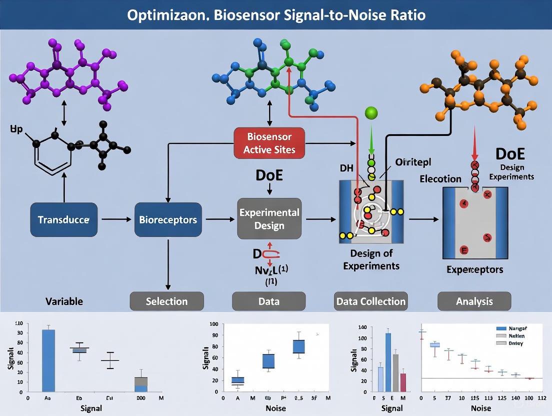
Optimizing Biosensor Performance: Using Design of Experiments to Overcome Signal-to-Noise Ratio Challenges
This article provides a comprehensive guide for researchers and drug development professionals on applying Design of Experiments (DoE) to enhance biosensor signal-to-noise ratios, a critical parameter for diagnostic accuracy and...
Optimizing Biosensor Performance: Using Design of Experiments to Overcome Signal-to-Noise Ratio Challenges
Abstract
This article provides a comprehensive guide for researchers and drug development professionals on applying Design of Experiments (DoE) to enhance biosensor signal-to-noise ratios, a critical parameter for diagnostic accuracy and reliability. It covers foundational principles of biosensor limitations and DoE methodology, explores practical applications through case studies in RNA quality control and electrochemical sensing, details systematic troubleshooting and optimization strategies, and validates the approach with performance comparisons. By synthesizing recent scientific advances, this resource offers a actionable framework for developing more sensitive, robust, and precise biosensing systems for biomedical and clinical applications.
Understanding the Bottleneck: Why Signal-to-Noise Ratio is a Critical Challenge in Biosensor Development
The Impact of Poor Signal-to-Noise on Diagnostic Sensitivity and Specificity
Technical Support Center
Troubleshooting Guides and FAQs
This technical support center provides solutions for researchers encountering signal-to-noise ratio (SNR) challenges in biosensor development, specifically framed within a Design of Experiments (DoE) research context.
FAQ 1: Why has my biosensor's diagnostic sensitivity dropped significantly during validation?
- Problem Identification: A sudden drop in sensitivity, leading to an increase in false negatives, often stems from a deteriorated signal-to-noise ratio (SNR). This prevents the biosensor from reliably detecting low analyte concentrations.
- DoE Framework Application: A degraded SNR can be systematically investigated using a Definitive Screening Design (DSD) to efficiently identify critical factors. Key factors to include in your experimental matrix are the concentrations of the reporter protein, binding oligonucleotides (e.g., poly-dT), and chemical environment modifiers like DTT [1].
- Troubleshooting Steps:
- Audit Reagent Integrity: Check the degradation status of enzymes, antibodies, or nucleic acid probes. Perform a calibration with a known standard.
- Re-optimize Assay Chemistry: Use a DSD to explore the interaction between reagent concentrations. For instance, systematically varying the concentration of a reducing agent like DTT can optimize the chemical environment for the reporter protein, potentially restoring signal strength [1].
- Verify Surface Functionalization: Confirm that the immobilization of biorecognition elements (e.g., thiol-tethered ssDNA) on the sensor surface has not been compromised, as poor density or orientation can drastically reduce the available signal [2].
FAQ 2: My biosensor is producing a high rate of false positives, impacting specificity. What components should I investigate?
- Problem Identification: High false positives, indicating low specificity, are frequently caused by non-specific binding (NSB), which increases background noise [3].
- DoE Framework Application: A factorial DoE can help optimize the "blocking" step. Test different types and concentrations of blocking agents (e.g., BSA, casein, proprietary blends) and detergents (e.g., Tween-20) simultaneously to find the combination that most effectively suppresses NSB without affecting the specific signal [3].
- Troubleshooting Steps:
- Enhance Blocking Protocols: Implement a DoE to find the optimal blocking buffer. This is a primary defense against NSB.
- Adjust Stringency Washes: Increase the number and/or stringency of wash steps post-sample application. A DoE can determine the optimal salt concentration and detergent percentage in wash buffers to dissociate weakly bound, non-specific molecules.
- Characterize Bioconjugates: Re-evaluate the quality of your signal labels (e.g., gold nanoparticles, enzymes). Aggregated labels or improper conjugation can lead to non-specific deposition and false signals [3].
FAQ 3: How can I systematically improve my biosensor's overall performance and Limit of Detection (LoD)?
- Problem Identification: A poor LoD is a direct consequence of an insufficient SNR. The goal is to maximize the specific signal while minimizing the inherent noise.
- DoE Framework Application: An iterative DSD approach is highly effective for this multi-parameter optimization. It allows you to move efficiently through the experimental design space toward an optimum by modeling main effects and two-factor interactions [1].
- Troubleshooting Steps:
- Iterative DoE Rounds: Do not stop after a single screening design. Use the results from an initial DSD to refine the factor ranges and perform a second round of optimization to further enhance dynamic range and lower the RNA concentration requirement [1].
- Incorporate Advanced Materials: Explore the use of signal-enhancing nanomaterials. For example, adding a monolayer of MoSe₂ to an SPR biosensor can significantly boost sensitivity and the signal-to-noise ratio by improving light-matter interaction [2].
- Refine Data Acquisition: For optical systems, ensure the light source is stable and the detector settings (e.g., integration time, gain) are optimized to reduce electronic noise. A simple DSD can help find the best settings.
Quantitative Data on SNR and Diagnostic Performance
The following table summarizes empirical data from published studies on how technological and optimization parameters influence key diagnostic metrics.
Table 1: Impact of Technical Factors on Diagnostic Accuracy
| Technology / Method | Key Factor | Impact on Sensitivity | Impact on Specificity | Overall Accuracy / Performance | Source |
|---|---|---|---|---|---|
| 68Ga-PSMA PET/CT (Prostate Cancer) | Imaging Technique & Radiotracer | Pooled Sensitivity: 80% (95% CI: 35–93) | Pooled Specificity: 90% (95% CI: 71–98) | Pooled Accuracy: 86% (95% CI: 64–96) | [4] |
| PSA Density (Prostate Cancer) | Cut-off Threshold (0.08 ng/mL/cc) | 98% | 16% | N/A | [5] |
| PSA Density (Prostate Cancer) | Cut-off Threshold (0.05 ng/mL/cc) | 99.6% | 3% | N/A | [5] |
| RNA Integrity Biosensor | DoE Optimization (Reporter, DTT, poly-dT levels) | N/A | N/A | 4.1-fold increase in dynamic range; LoD reduced by one-third | [1] |
| FFRCT (Coronary Artery Disease) | Low SNR / Image Artifacts | Maintained High Performance | Maintained High Performance | Diagnostic Accuracy remained superior to CT stenosis (86% with artifacts) | [6] |
| MoSe₂-based SPR Biosensor | 2D Nanomaterial (MoSe₂) Layer | Sensitivity: 197.70°/RIU | Enhanced via improved SNR | Detection Accuracy: 5.24 x 10⁻²; LoD: 2.53 x 10⁻⁵ | [2] |
Detailed Experimental Protocols
Protocol 1: Iterative Definitive Screening Design (DSD) for Biosensor Optimization
This protocol is adapted from the optimization of an RNA integrity biosensor [1].
- Define Factors and Ranges: Select critical assay components (e.g., Reporter Protein concentration, Oligonucleotide concentration, DTT concentration, MgCl₂ concentration, incubation time) and assign a high and low level for each based on prior knowledge.
- Generate Experimental Matrix: Use statistical software to create a DSD, which requires only a minimal number of runs to screen for important main effects and two-factor interactions.
- Execute Experiments: Perform the biosensor assay according to the randomized run order provided by the DSD.
- Measure Responses: Quantify key output responses such as Signal Intensity, Background Noise, Dynamic Range, and calculated Signal-to-Noise Ratio.
- Statistical Analysis and Model Fitting: Analyze the data using a stepwise model with a Bayesian information criterion (BIC). This will identify which factors have significant main or interaction effects on your responses.
- Iterate and Refine: Use the model from the first DSD to define a new, narrower range of factors for a subsequent round of optimization to converge on the global optimum.
Protocol 2: Functionalizing an SPR Biosensor with a MoSe₂ Layer for Enhanced SNR
This protocol is based on the mathematical modeling and development of a biosensor for SARS-CoV-2 detection [2].
- Substrate Preparation: Begin with a BK7 prism as the core optical component.
- Metal Layer Deposition: Deposit a 45 nm thick layer of Silver (Ag) onto the prism. This layer is responsible for generating the surface plasmon polaritons.
- Adhesion and Coupling Layer: Apply a thin layer (e.g., 10 nm) of Silicon Nitride (Si₃N₄) to protect the silver and provide a suitable surface for the 2D material.
- 2D Nanomaterial Transfer: Transfer a monolayer of Molybdenum Diselenide (MoSe₂) onto the Si₃N₄ layer. This enhances the electric field and light-matter interaction, boosting sensitivity.
- Probe Immobilization: Functionalize the MoSe₂ surface with a 10 nm thick layer of thiol-tethered single-stranded DNA (ssDNA) designed to be complementary to your target analyte (e.g., viral RNA).
- Validation: Characterize the biosensor's performance by measuring the shift in the resonance angle (Δθ) in response to known concentrations of the target analyte, calculating the sensitivity (°/RIU), and determining the Limit of Detection (LoD).
Signaling Pathways and Experimental Workflows
The Scientist's Toolkit: Research Reagent Solutions
Table 2: Essential Materials for Biosensor Development and Optimization
| Reagent / Component | Function in Biosensor Development | Example from Literature |
|---|---|---|
| Thiol-tethered ssDNA | Acts as a biorecognition probe; thiol group allows for stable immobilization on metal (e.g., gold) or nanomaterial surfaces [2]. | Used to functionalize a MoSe₂-based SPR biosensor for specific capture of SARS-CoV-2 RNA [2]. |
| Dithiothreitol (DTT) | A reducing agent that maintains a stable chemical environment for protein-based reporters, preventing oxidation and loss of function [1]. | Optimization of DTT concentration via DoE increased biosensor dynamic range [1]. |
| Blocking Agents (e.g., BSA, Casein) | Used to cover unused binding sites on the sensor surface, thereby minimizing non-specific binding and reducing background noise [3]. | Critical for improving specificity in lateral flow immunoassays and other biosensor formats [3]. |
| Detergents (e.g., Tween-20) | Surfactants added to wash and running buffers to reduce hydrophobic interactions and further minimize non-specific binding [3]. | A key component in buffer optimization for assay development [3]. |
| Transition Metal Dichalcogenides (e.g., MoSe₂) | 2D nanomaterials used to enhance the signal in optical biosensors due to their strong light-matter interaction and high refractive index [2]. | A monolayer of MoSe₂ significantly boosted the sensitivity and SNR of an SPR biosensor [2]. |
| Reporter Proteins (e.g., B4E fusion protein) | Engineered proteins that bind to specific targets (e.g., m7G cap of RNA) and generate a detectable signal (e.g., colorimetric change) [1]. | The concentration of the B4E reporter was a key factor optimized via DoE [1]. |
This technical support center provides a structured guide to diagnosing and mitigating noise in biosensing systems. A thorough understanding of noise sources—from electronic to biochemical interference—is foundational to improving the signal-to-noise ratio (SNR), a critical performance parameter. This resource frames troubleshooting protocols within the powerful, systematic framework of Design of Experiments (DoE), a statistical methodology that moves beyond traditional one-factor-at-a-time approaches to efficiently identify optimal conditions and interaction effects that impact noise [7] [8]. The following guides and FAQs are designed to help researchers and drug development professionals pinpoint specific issues in their experiments and apply data-driven strategies for enhancement.
Troubleshooting Guides
Guide 1: Diagnosing and Mitigating Electronic Noise
Problem: Your biosensor exhibits high baseline fluctuations, erratic signals in low-concentration measurements, or poor low-frequency performance.
Objective: To identify the source of electronic noise and implement corrective actions to stabilize the signal baseline.
Experimental Protocol for Diagnosis:
- Baseline Recording: With no analyte present, record the baseline output of your biosensor in a clean, physiologically relevant buffer (e.g., PBS) for at least 10 minutes.
- Shielding Test: Enclose the sensor and its immediate connections in a Faraday cage. Record the baseline again for 10 minutes. A significant reduction in fluctuation indicates environmental electromagnetic interference (EMI).
- Thernal Stability Test: Place the sensor setup in a temperature-controlled environment (e.g., an incubator). Record the output at different stable temperatures (e.g., 25°C, 37°C). Correlate signal drift with temperature changes to identify Johnson-Nyquist noise susceptibility.
- Frequency Analysis: Use a spectrum analyzer to examine the power spectral density (PSD) of the baseline signal. A
1/f(pink noise) spectrum dominating at low frequencies suggests flicker noise, while a flat (white noise) spectrum suggests thermal noise [9] [10].
Interpretation and Solutions:
- If the Shielding Test reduced noise: The primary culprit is Environmental EMI. Secure all cabling, use shielded cables and enclosures, and operate the setup away from power lines and wireless communication devices [9].
- If the Thermal Stability Test showed drift: Thermal (Johnson-Nyquist) Noise is significant. Ensure temperature control for sensitive measurements. For the sensor itself, select materials with lower electrical resistance where possible, as thermal noise is proportional to resistance and temperature [9] [11].
- If Frequency Analysis showed high
1/fnoise: Flicker Noise originates from material imperfections and interfaces. Consider using electrode materials with fewer defects, such as high-quality, crystalline carbon nanomaterials over traditional polycrystalline metals, to reduce this low-frequency noise [9] [12].
Guide 2: Managing Biochemical Interference and Non-Specific Binding
Problem: Your sensor shows high signal in negative controls, inconsistent calibration, or drift when used with complex biological samples like serum, blood, or saliva.
Objective: To confirm and reduce signal noise arising from non-specific binding (NSB) of interfering molecules in the sample matrix.
Experimental Protocol for Diagnosis:
- Negative Control with Matrix: Run your standard assay using a sample that does not contain the target analyte but contains the complete biological matrix (e.g., analyte-free serum).
- Compare with Buffer Control: Run the same negative control with a simple buffer (e.g., PBS). A significantly higher signal in the matrix control confirms substantial NSB and biochemical noise.
- DoE for Surface Blocking (Example): To efficiently find the best blocking conditions, use a DoE screening design. For example, a 2-factor, 2-level design can optimize blocker concentration and incubation time.
- Factors: Blocker Concentration (e.g., BSA: 0.1% vs. 1.0%), Incubation Time (5 min vs. 30 min).
- Response: Signal from the matrix-only negative control (aim to minimize).
- This 4-experiment design can identify the main effects and interaction between these two factors, leading to a more robust blocking protocol than testing one variable at a time [7] [8].
Interpretation and Solutions:
- Surface Passivation: The standard solution is to use blocking agents like Bovine Serum Albumin (BSA) or polyethylene glycol (PEG) to passivate unused surface sites [9].
- Advanced Materials: For persistent issues, consider transducers with innate antifouling properties. Novel carbon nanomaterials have demonstrated an ability to drastically reduce NSB without additional coatings, thereby preserving signal strength and improving reproducibility in complex matrices [9].
- Sample Pre-treatment: For exceptionally "dirty" samples, introduce dilution, filtration, or precipitation steps to remove interfering components before analysis.
Guide 3: Characterizing Dynamic Response and Intrinsic Noise
Problem: Your biosensor has a slow response time, making real-time monitoring difficult, or you need to understand the fundamental noise floor for limit-of-detection (LOD) calculations.
Objective: To model the temporal response and quantify the intrinsic noise of the biosensing mechanism, particularly for adsorption-based sensors.
Experimental Protocol for Diagnosis:
- Step-Change Experiment: Introduce a rapid concentration step of your analyte and record the sensor's output at a high sampling rate until a new steady state is reached.
- Kinetic Fitting: Fit the response data to kinetic models. A single-exponential fit may suffice for simple systems. If the response shows a fast initial rise followed by a slower approach to steady-state, a two-exponential model is required, indicating a two-step process like adsorption followed by biomolecular rearrangement [10].
- Noise Spectral Analysis: Under steady-state conditions (with a constant analyte concentration), record the output for a prolonged period. Calculate the Power Spectral Density (PSD) of the signal fluctuations. This reveals the characteristic frequencies of the intrinsic noise, which can be linked to underlying stochastic processes like adsorption, desorption, and rearrangement [10].
Interpretation and Solutions:
- Slow Response: If kinetics are limited by biomolecular rearrangement post-adsorption, this may be an inherent property of the analyte-receptor pair. The solution is to account for it in your response model to avoid misinterpretation of real-time data [10].
- Noise Floor: The magnitude of the low-frequency noise in the PSD sets a fundamental limit on your sensor's resolution and LOD. This information is critical for performance estimation and cannot be reduced by signal averaging alone; it requires changes to the sensing chemistry or interface [10].
Frequently Asked Questions (FAQs)
Q1: My biosensor works perfectly in buffer but fails in real blood samples. What should I do? This is a classic symptom of biofouling and non-specific binding. The complex matrix of blood contains countless proteins, lipids, and cells that adhere to your sensor's surface. Implement a robust surface blocking protocol using agents like BSA or PEG. If the problem persists, investigate biosensor platforms that use novel carbon nanomaterials with demonstrated innate antifouling properties, which prevent NSB without sacrificing signal sensitivity [9].
Q2: What is the most efficient way to optimize multiple assay conditions (like pH, temperature, and concentration) simultaneously? The most efficient and statistically sound method is to use a Design of Experiments (DoE) approach. Traditional one-factor-at-a-time (OFAT) optimization is inefficient and can miss critical interactions between factors. A fractional factorial design, such as a Plackett-Burman design, can screen many factors to identify the most important ones with minimal experimental runs. Subsequently, a response surface methodology (RSM), like a Central Composite Design, can be used to find the optimal settings for these key factors [7] [8] [1].
Q3: I am using a FET-based biosensor and my sensitivity is lower than expected. What could be wrong? For FET-based biosensors, sensitivity is closely tied to the properties of the dielectric layer and the location of the sensing cavity. A cavity positioned between gate electrodes can compromise the device's ability to modulate the channel effectively, reducing sensitivity. Furthermore, noise from random dopant fluctuations or a high thermal budget during fabrication can degrade the signal-to-noise ratio. Consider device architectures with the cavity strategically placed under the control gate and ensure fabrication processes minimize intrinsic electronic noise sources [11] [12].
Q4: How can I distinguish between electronic noise and noise from the biological sensing process itself? The key is to perform a frequency domain analysis. Electronic noise, such as thermal and flicker noise, has a specific signature in the power spectral density (PSD). Biological processes, such as the stochastic adsorption and rearrangement of biomolecules, generate noise with different characteristic frequencies. By analyzing the PSD of your sensor's output under steady-state conditions, you can identify the contributions of each noise source. A model that includes terms for adsorption, desorption, and rearrangement is necessary to correctly interpret the noise arising from the biochemical interaction [10].
Quantitative Data Reference
Table 1: Common Electronic Noise Types and Mitigation Strategies
| Noise Type | Root Cause | Key Characteristics | Effective Mitigation Strategies |
|---|---|---|---|
| Thermal (Johnson-Nyquist) | Random thermal motion of charge carriers [9] | White noise spectrum; proportional to √(R × T) [9] | Cool the system; use lower-resistance materials [9] [11] |
| Flicker (1/f) | Material imperfections & traps at interfaces [9] [11] | Dominates at low frequencies; ~1/f^α spectrum [9] | Use high-quality, defect-free electrode materials (e.g., carbon nanomaterials) [9] [12] |
| Environmental EMI | External sources like power lines & wireless devices [9] | Can cause large, sporadic baseline shifts | Use Faraday cages, shielded cables, proper grounding [9] |
Table 2: DoE Optimization of an RNA Biosensor: Performance Improvement Summary [1]
| Performance Metric | Before DoE Optimization | After DoE Optimization | Improvement Factor |
|---|---|---|---|
| Dynamic Range | Baseline | 4.1-fold increase | 4.1x |
| RNA Sample Required | Baseline | Reduced by one-third | ~66% of original |
| Key Factor Changes | --- | Reduced reporter protein & poly-dT; Increased DTT | --- |
Essential Visualizations
Diagram 1: Biosensor Noise Classification and Mitigation Pathways
Diagram 2: Systematic DoE Workflow for Biosensor Optimization
The Scientist's Toolkit: Key Reagents & Materials
Table 3: Essential Research Reagents for Noise Mitigation
| Reagent/Material | Primary Function in Noise Reduction | Example Use Case |
|---|---|---|
| Bovine Serum Albumin (BSA) | Blocking agent to passivate sensor surface and reduce non-specific binding from proteins in complex samples [9] [1]. | Incubated on sensor surface after probe immobilization, before sample introduction. |
| Polyethylene Glycol (PEG) | Polymer used as an antifouling coating to create a hydrophilic, neutral layer that repels biomolecules [9]. | Grafted onto transducer surfaces to minimize biofouling in serum or whole blood. |
| Dithiothreitol (DTT) | Reducing agent that maintains a stable chemical environment for biomolecular interactions, optimizing biosensor performance [1]. | Added to assay buffer to break disulfide bonds and prevent unwanted protein aggregation. |
| Carbon Nanomaterials | Transducer materials with high conductivity, innate antifouling properties, and low flicker noise due to fewer grain boundaries [9]. | Used as the electrode material in electrochemical biosensors for sensitive detection in complex matrices. |
| Poly-dT Oligonucleotide | Capture probe for binding poly-A tails of mRNA targets in RNA integrity biosensors; its concentration is a key factor for dynamic range [1]. | Immobilized on magnetic beads or sensor surfaces to specifically capture mRNA molecules. |
Limitations of Traditional One-Factor-at-a-Time (OFAT) Optimization Approaches
Frequently Asked Questions (FAQs)
1. What is the main drawback of using OFAT for optimizing my biosensor's performance?
The primary limitation is that OFAT fails to detect interactions between factors. When you optimize one factor at a time while holding others constant, you cannot see how the effect of one variable might change at different levels of another variable [7] [13]. In biosensor development, factors like pH, temperature, and immobilization strategy often interact. OFAT risks missing the true optimal combination of conditions, potentially leading to a suboptimal signal-to-noise ratio (SNR) [7] [8].
2. My OFAT experiment found a configuration that improved the signal. Why shouldn't I use it?
While OFAT can yield improvements, the result is likely suboptimal [7] [14]. The final configuration is highly dependent on the order in which you choose to optimize the variables [7]. You may have found a local maximum in performance, but by not testing factor combinations, you can easily miss a different set of conditions that would provide a much greater enhancement of your biosensor's signal-to-noise ratio [14] [13].
3. Is OFAT ever a suitable method for biosensor optimization?
OFAT may be considered only for systems that are proven to be exceptionally simple, where there is high confidence that only one variable affects the outcome and that no interactions exist between variables [14]. However, for complex systems like ultrasensitive biosensors—where challenges with signal-to-noise ratio, selectivity, and reproducibility are pronounced—a multivariate approach like Design of Experiments (DoE) is strongly recommended [8].
4. How does the one-factor-at-a-time approach impact resource use in the long run?
Although OFAT seems intuitively straightforward, it can be time and resource intensive due to the extensive number of experimental iterations required, especially as the number of variables grows [7]. More critically, because it often leads to a suboptimal solution, you may waste resources developing a biosensor with inferior performance, or be forced to re-optimize the system later, ultimately costing more than using a multivariate approach from the beginning [14].
Troubleshooting Guides
Problem: After an OFAT optimization, my biosensor's performance is unstable or inconsistent.
- Potential Cause: The OFAT approach may have identified optimal conditions for one factor that are only effective at the specific, fixed levels of the other factors you chose during the process. In a real-world setting, these factors can vary, revealing unfavorable interactions that OFAT could not detect [7].
- Solution: Transition to a multivariate approach. Use a screening design, such as a Plackett-Burman or Definitive Screening Design (DSD), to efficiently identify which factors and factor interactions have the most significant impact on your biosensor's stability [7]. This will help you find a robust operational window.
Problem: I cannot achieve the desired signal-to-noise ratio despite OFAT optimization.
- Potential Cause: OFAT is ineffective at navigating complex response surfaces and can easily get trapped in a local performance maximum, preventing you from discovering the true global optimum needed for an ultrasensitive biosensor [8] [13].
- Solution: Employ an optimization-focused DoE like Response Surface Methodology (RSM). Methods like Central Composite Design (CCD) or Box-Behnken Design (BBD) will help you model the curvature of the response and pinpoint the factor settings that truly maximize SNR [7] [8].
Problem: My experimental results from an OFAT protocol are difficult to interpret or seem contradictory.
- Potential Cause: Unaccounted-for interactions between factors are distorting the results. For example, the effect of changing the immobilization pH might be different at a high temperature than it is at a low temperature [13].
- Solution: Analyze your system using a full factorial design. This allows you to not only estimate the individual effect of each factor but also to quantify the interaction effects between them, resolving the apparent contradictions in your data [7] [15].
Comparative Data: OFAT vs. DoE
The table below summarizes a quantitative comparison between OFAT and DoE approaches for a two-factor optimization, illustrating the efficiency of DoE [13].
| Aspect | One-Factor-at-a-Time (OFAT) | Design of Experiments (DoE) |
|---|---|---|
| Total Experimental Runs | 13 runs (7 for Temperature + 6 for pH) [13] | 12 runs (including replicates) [13] |
| Detected Maximum Yield | 86% [13] | 92% (predicted and confirmed) [13] |
| Interaction Detection | No, cannot detect interaction between factors [13] | Yes, clearly identifies and models interaction [13] |
| Model Capability | Provides only a local, incomplete view of the process [7] | Creates a predictive model for the entire design space [8] [13] |
| Experimental Efficiency | Low; number of runs grows rapidly with more factors [7] | High; efficiently explores multiple factors simultaneously [7] [13] |
Experimental Protocols: Key Methodologies
Protocol 1: Screening for Significant Factors using a Plackett-Burman Design
- Define Factors and Levels: List all potential factors that could influence your biosensor's SNR (e.g., probe concentration, buffer ionic strength, incubation time, temperature). Assign a "high" (+1) and "low" (-1) level to each factor based on preliminary knowledge [7].
- Generate Design Matrix: Use statistical software to create a Plackett-Burman design matrix. This matrix specifies the set of factor level combinations to be run, which is a fraction of a full factorial design, making it highly efficient for screening [7].
- Randomize and Execute: Randomize the run order of the experiments specified by the matrix to minimize the effect of confounding variables. Prepare your biosensors according to each specified combination and measure the response (e.g., signal intensity and noise) [16] [15].
- Analyze Results: Perform statistical analysis (e.g., analysis of variance) to identify which factors have a statistically significant effect on the response. Focus further optimization efforts on these significant factors [7] [14].
Protocol 2: Optimizing with Response Surface Methodology (Central Composite Design)
- Select Critical Factors: Choose the 2-4 most important factors identified from your initial screening design [8].
- Create CCD Matrix: A Central Composite Design builds upon a factorial design by adding axial (star) points and center points. This allows for the estimation of curvature in the response surface, which is critical for finding a true optimum [7] [8].
- Run Experiments and Build Model: Execute the experiments in random order. Use the data to fit a quadratic model that describes the relationship between the factors and your response (e.g., SNR) [8].
- Validate and Predict: Use the model to generate response surface and contour plots. Identify the optimal factor settings predicted by the model and run confirmation experiments to validate the prediction [13].
Experimental Workflow Visualization
Research Reagent Solutions
The following table details key materials and their functions relevant to optimizing biosensor fabrication and performance [17] [8].
| Reagent/Material | Function in Biosensor Optimization |
|---|---|
| Biolayer Components | Forms the sensitive interface for specific recognition of target molecules; its composition is a critical factor for signal generation [8]. |
| Immobilization Reagents | Chemicals or linkers used to attach biorecognition elements (e.g., antibodies, enzymes) to the transducer surface; optimization is key to maintaining bioactivity [8]. |
| Buffer Solutions | Control the pH and ionic strength of the sensing environment, which significantly affects biorecognition efficiency and signal-to-noise ratio [7] [8]. |
| Standardized Reporter Constructs | Genetically encoded elements (e.g., promoters, RBSs) with quantitatively characterized strengths; allow for treatment of genetic parts as continuous variables in a DoE [7]. |
What is Design of Experiments (DoE)? Design of Experiments (DoE) is a structured, organized method for determining the relationships between factors affecting a process and its output. In biosensor development, DoE provides a systematic framework for optimizing multiple parameters simultaneously, enabling researchers to gain maximum information from a minimum number of experiments while accounting for variability and identifying critical interactions between process parameters [18].
Why is DoE Critical for Biosensor Signal-to-Noise Ratio Optimization? Biosensor accuracy and sensitivity remain significant barriers to widespread industrial, healthcare, and diagnostic applications [19]. A biosensor's performance is characterized by several key attributes, with sensitivity (limit of detection) and stability being particularly crucial for reliable measurements [20]. The signal-to-noise ratio directly impacts the minimum detectable concentration of an analyte, which is essential for applications requiring ultra-sensitive detection, such as early disease diagnosis where biomarkers may be present at femtomolar concentrations or lower [8].
Traditional one-factor-at-a-time optimization approaches often fail to identify complex interactions between multiple parameters affecting biosensor performance. DoE addresses this limitation by systematically exploring the entire experimental domain, enabling researchers to develop data-driven models that connect variations in input parameters to biosensor outputs [8]. This approach is particularly valuable for ultrasensitive biosensing platforms where enhancing signal-to-noise ratio, improving selectivity, and ensuring reproducibility are paramount challenges.
Table 1: Key Biosensor Performance Characteristics Impacted by DoE Optimization
| Performance Characteristic | Description | Importance in Biosensing |
|---|---|---|
| Sensitivity (Limit of Detection) | Minimum amount of analyte that can be detected | Critical for early disease diagnosis; determines clinical utility |
| Selectivity | Ability to detect specific analyte in sample containing admixtures | Prevents false positives/negatives; ensures accurate diagnosis |
| Reproducibility | Ability to generate identical responses for duplicated experiments | Essential for regulatory approval and clinical adoption |
| Stability | Degree of susceptibility to ambient disturbances | Crucial for applications requiring long incubation or continuous monitoring |
| Linearity | Accuracy of measured response to a straight line | Determines concentration measurement range and resolution |
Fundamental DoE Methodology and Workflow
DoE implementation follows a systematic workflow that begins with clear objective definition and progresses through experimental design, execution, analysis, and validation. The fundamental principle of DoE is to make deliberate changes to input variables (factors) to observe corresponding changes in output variables (responses), then use statistical analysis to build predictive models of system behavior [18].
Core DoE Principles
Three fundamental principles form the foundation of proper DoE implementation:
Randomization: Performing experimental runs in random order to minimize the effects of uncontrolled variables and satisfy statistical assumptions of independence [18].
Replication: Repeating experimental runs to obtain an estimate of experimental error (pure error) and improve parameter estimation precision [18].
Blocking: Grouping experimental runs to account for known sources of variation that are not primary factors of interest, such as different equipment, operators, or material batches [18].
Experimental Design Types
Different experimental designs serve distinct purposes in the optimization process:
Full Factorial Designs: Systematically examines all possible combinations of factors and levels, enabling complete characterization of main effects and interactions. A 2^k factorial design requires 2^k experiments, where k represents the number of variables being studied [8].
Central Composite Designs: Augments factorial designs with additional points to estimate curvature, making them suitable for fitting second-order (quadratic) response models [8].
Mixture Designs: Specialized designs for situations where the combined total of all components must equal 100%, requiring proportional adjustment of components when one changes [8].
Figure 1: Systematic DoE Workflow for Biosensor Optimization
Practical Implementation of DoE for Biosensor Development
Pre-Experimental Planning
Setting SMART Objectives Before beginning experimentation, researchers must establish Specific, Measurable, Attainable, Realistic, and Time-based (SMART) objectives. This focuses the team on specific aims and helps manage resources and expectations [18]. For biosensor development, typical objectives might include "achieving a detection limit of ≤1 fM for target biomarker X while maintaining a signal-to-noise ratio ≥10:1 within 3 weeks of experimental effort."
Factor Selection and Range Determination Selecting appropriate process parameters and their investigation ranges is critical. Risk assessment methodologies like Failure Mode and Effect Analysis (FMEA) or cause-and-effect (fishbone) diagrams systematically identify parameters with potential impact on biosensor performance [18]. The investigation range must be carefully balanced—too narrow a range may miss important effects, while too wide a range may exceed practical manufacturing constraints. A good practice is to set levels approximately 1.5-2.0× the equipment or process capability for robustness studies, and 3-4× the desired operating range for screening studies [18].
Table 2: Common Biosensor Parameters for DoE Optimization
| Parameter Category | Specific Parameters | Typical Range Considerations |
|---|---|---|
| Biorecognition Elements | Antibody concentration, Aptamer density, Enzyme loading | Vary around reported optimal values (±30-50%) |
| Transducer Interface | Electrode surface area, Nanomaterial concentration, Immobilization time | Based on physical constraints of system |
| Membrane Properties | Porosity, Thickness, Wettability | Manufacturer specifications ± feasible processing range |
| Sample Processing | Flow rate, Incubation time, Temperature | Physiological relevance ± practical operating limits |
| Detection Conditions | pH, Ionic strength, Applied potential | Compatibility with biological components |
DoE Experimental Designs for Biosensor Optimization
Screening Designs Initial DoE applications in biosensor development often focus on identifying the most influential factors from a large set of potential parameters. Fractional factorial designs or Plackett-Burman designs efficiently screen 5-20 factors with a minimal number of experimental runs, helping researchers focus optimization efforts on the truly critical parameters [3] [8].
Response Surface Methodology For detailed optimization of critical parameters, Response Surface Methodology (RSM) with central composite or Box-Behnken designs enables modeling of quadratic response surfaces. This approach is particularly valuable for identifying optimal operating conditions that maximize biosensor signal-to-noise ratio while minimizing false-positive and false-negative responses [19] [8].
Mixture Designs In biosensor formulation development where components must sum to 100% (e.g., reagent mixtures, membrane compositions), mixture designs provide specialized methodology for exploring the experimental space while respecting this constraint [8].
Essential Research Reagents and Materials for Biosensor DoE
Successful implementation of DoE in biosensor development requires careful selection and control of research reagents and materials. The following table outlines key components and their functions in biosensor systems.
Table 3: Essential Research Reagent Solutions for Biosensor Development
| Reagent/Material | Function | DoE Optimization Considerations |
|---|---|---|
| Biorecognition Elements (Antibodies, aptamers, enzymes, nucleic acids) | Molecular recognition of target analyte | Concentration, immobilization density, orientation, specificity [3] |
| Nanomaterial Labels (Gold nanoparticles, quantum dots, magnetic beads) | Signal generation and amplification | Size, shape, surface chemistry, functionalization [3] [21] |
| Membrane Components (Nitrocellulose, PVDF, cellulose) | Fluid control and reagent immobilization | Porosity, thickness, capillary flow rate, protein binding capacity [3] |
| Blocking Agents (BSA, casein, synthetic blockers) | Minimize non-specific binding | Type, concentration, incubation time, compatibility with detection system [3] |
| Detergents/Surfactants (Tween-20, Triton X-100) | Modify surface tension and reduce non-specific binding | Type, concentration, impact on biorecognition element activity [3] |
| Signal Development Reagents (Enzyme substrates, chemiluminescent reagents) | Generate detectable signal | Concentration, reaction time, stability, compatibility with detection method [22] |
DoE Protocols for Biosensor Signal-to-Noise Optimization
Protocol 1: Screening Critical Factors in Biosensor Fabrication
Objective: Identify critical factors influencing biosensor signal-to-noise ratio from a set of 5-7 potential parameters.
Materials:
- Biorecognition elements (e.g., antibodies, aptamers)
- Transducer platform (e.g., electrode strips, membrane)
- Nanomaterial labels (e.g., gold nanoparticles, quantum dots)
- Blocking buffers and washing solutions
- Target analyte standards
Experimental Design:
- Select 5-7 potential critical factors based on risk assessment (e.g., antibody concentration, nanomaterial label density, blocking time, membrane type, incubation temperature).
- Implement a fractional factorial design (e.g., 2^(5-1) or 2^(6-2)) with 4-6 center points to estimate experimental error.
- Randomize run order to minimize confounding from external factors.
- For each experimental run, fabricate 3-5 replicate biosensors to account for manufacturing variability.
- Measure response for each biosensor using appropriate positive and negative controls.
Response Measurements:
- Signal-to-noise ratio (positive control signal/negative control signal)
- Limit of detection (lowest measurable concentration with signal ≥ 3× standard deviation of blank)
- Assay variability (coefficient of variation for replicates)
Statistical Analysis:
- Calculate main effects for each factor.
- Identify significant factor interactions using ANOVA (p < 0.05).
- Validate model adequacy using residual analysis.
- Select 2-3 most critical factors for further optimization [8] [18].
Protocol 2: Response Surface Optimization of Biosensor Performance
Objective: Optimize critical factors identified from screening to maximize signal-to-noise ratio while minimizing false responses.
Materials:
- Biorecognition elements at varying concentrations
- Optimized transducer platform
- Signal amplification reagents
- Target analyte across concentration range (including near-LOD concentrations)
Experimental Design:
- Select 2-3 critical factors identified from screening experiments.
- Implement a Central Composite Design (CCD) with 4-6 center points and α = 1.414 (face-centered) or 1.682 (rotatable).
- Include 4-5 replicate measurements at the center point to estimate pure error.
- Block experiments if necessary to account for day-to-day variability.
Response Measurements:
- Signal-to-noise ratio across analyte concentration range
- False-positive and false-negative rates [19]
- Assay Z'-factor (for high-throughput applications) [22]
Statistical Analysis:
- Fit second-order polynomial model to response data.
- Evaluate model significance and lack-of-fit using ANOVA.
- Generate response surface and contour plots to visualize factor relationships.
- Identify optimal operating conditions using desirability functions.
- Validate predicted optimum with 3-5 confirmation experiments [8] [18].
Figure 2: Response Surface Methodology Workflow
Troubleshooting Guide: Common DoE Implementation Challenges
FAQ 1: Why does my DoE model show poor predictive capability despite significant factors?
Problem: The mathematical model developed from DoE results has poor predictive power, even when ANOVA indicates significant factors.
Potential Causes and Solutions:
- Insufficient model hierarchy: Include lower-order terms even if non-significant when higher-order terms are significant.
- Inadequate factor range: The selected range for factors may be too narrow to detect meaningful changes relative to experimental error. Expand factor ranges to 1.5-2× current range [18].
- Unaccounted noise sources: Identify and control major sources of variability through blocking or inclusion as experimental factors.
- Response measurement error: Ensure measurement system variability (repeatability and reproducibility) is <20%, ideally 5-15% for biological systems [18].
- Missing important factors: Revisit risk assessment to identify potentially critical factors not included in initial design.
FAQ 2: How can I address high variability in biosensor responses during DoE studies?
Problem: High replicate variability obscures factor effects and reduces experimental sensitivity.
Potential Causes and Solutions:
- Inconsistent fabrication techniques: Standardize fabrication protocols and operator training.
- Bioreceptor instability: Implement proper storage conditions and freshness controls for biological recognition elements [3].
- Environmental fluctuations: Control temperature, humidity, and light exposure during fabrication and testing.
- Measurement instrumentation: Calibrate instruments regularly and maintain consistent measurement conditions.
- Solution: Increase replication at center points, implement blocking for known variability sources, and consider nested designs to separate different variability sources [18].
FAQ 3: How do I handle situations where my biosensor responses don't follow normal distribution?
Problem: Residual analysis indicates non-normal distribution of errors, violating statistical assumptions.
Potential Causes and Solutions:
- Inherently non-normal response: Consider data transformation (log, square root, Box-Cox) to normalize error distribution.
- Outlier responses: Investigate special causes for outlier data points rather than automatically excluding them.
- Saturated response: If response approaches physical limits (e.g., signal saturation), consider alternative measurement approach or model.
- Alternative approaches: Use generalized linear models or non-parametric analysis methods if transformations are ineffective.
FAQ 4: What is the optimal approach for balancing model complexity with experimental resources?
Problem: Limited resources constrain the number of experimental runs, potentially compromising model quality.
Potential Causes and Solutions:
- Sequential approach: Begin with screening designs to identify critical factors, followed by optimization designs focusing only on those factors [8].
- D-optimal designs: Use computer-generated D-optimal designs when classical designs require too many runs for available resources.
- Fractional factorial designs: Implement highly fractionated designs for initial screening, recognizing that some interactions will be confounded.
- Leverage prior knowledge: Incorporate historical data or literature findings to reduce experimental burden for well-characterized factors.
Advanced DoE Applications in Biosensor Research
DoE for Reducing Biosensor False Responses
Recent research demonstrates that integrating machine learning with DoE principles can significantly reduce false-positive and false-negative results in biosensing applications. By treating analyte concentration as a categorical variable and applying classification algorithms to dynamic biosensor response data, researchers can achieve accurate quantification while minimizing false responses [19]. Theory-guided feature engineering further enhances model performance by incorporating domain knowledge about biosensor behavior.
DoE for Accelerated Biosensor Development
The systematic approach of DoE enables more efficient biosensor optimization compared to traditional one-factor-at-a-time methods. Case studies report that DoE can offer returns that are four to eight times greater than the cost of running the experiments in a fraction of the time [18]. This acceleration is particularly valuable for developing biosensors for emerging pathogens or rapidly evolving diagnostic needs.
DoE in Nanomaterial-Enhanced Biosensors
The integration of nanomaterials in biosensors introduces additional complexity due to multiple optimization parameters including nanomaterial size, shape, surface functionalization, and incorporation density. DoE provides a structured approach to optimize these parameters simultaneously, ensuring enhanced sensitivity and specificity while maintaining biosensor reproducibility and stability [3] [21].
Design of Experiments provides an powerful systematic framework for addressing the complex challenge of biosensor signal-to-noise ratio optimization. By enabling efficient exploration of multiple factors and their interactions, DoE facilitates the development of ultrasensitive biosensors with enhanced reliability and reduced false responses. The methodology's emphasis on structured planning, statistical rigor, and model-based optimization aligns perfectly with Quality by Design principles increasingly demanded in diagnostic and pharmaceutical development.
As biosensing technologies evolve toward increasingly sophisticated applications—including point-of-care diagnostics, continuous monitoring, and multiplexed detection—the role of DoE in ensuring robust performance will only grow in importance. By adopting the protocols, troubleshooting guidelines, and best practices outlined in this technical support document, researchers can systematically overcome signal-to-noise challenges and accelerate the development of next-generation biosensing platforms.
Troubleshooting Guides
Guide 1: Troubleshooting a Poor Signal-to-Noise Ratio in Biosensor Development
Problem: The output signal from a biosensor is weak and obscured by background noise, making reliable detection difficult.
Application Context: This is a common challenge when developing enzymatic or microbial bioelectronic sensors, where weak electrical signals can be drowned out by environmental or system noise [23] [24].
1. Check Process Stability and Measurement System
- Potential Cause: Unstable process conditions or an unverified measurement system introduce uncontrolled variation, masking the true signal [16].
- Solution: Before any Design of Experiments (DoE), ensure your biosensor production and testing process is stable. Use Statistical Process Control (SPC) charts to verify consistency. Perform a Measurement System Analysis (MSA), such as a Gage R&R study, to confirm your instruments are calibrated and provide repeatable, reliable data [16].
2. Screen for Key Factors Affecting Signal Fidelity
- Potential Cause: Too many potential factors are being considered at once, making it impossible to identify the few that critically influence the signal-to-noise ratio [25].
- Solution: Use a screening DoE to efficiently identify the "vital few" factors from the "trivial many" [26]. A Plackett-Burman design or a two-level fractional factorial design is ideal for this initial stage, as it requires minimal runs to pinpoint significant factors like specific buffer conditions or transducer materials [7] [25].
3. Optimize Critical Factors for Maximum Response
- Potential Cause: The important factors identified during screening are not set at their optimal levels [27].
- Solution: Employ a Response Surface Methodology (RSM) design, such as a Central Composite Design (CCD) or Box-Behnken Design (BBD) [27] [7]. These designs help you model curvature and find the precise factor settings (e.g., optimal enzyme concentration or pH) that maximize the output signal [27].
4. Integrate Amplification Components
- Potential Cause: The inherent signal from the bio-recognition element is too weak for your detection system [23].
- Solution: Consider electronic signal amplification. Recent research demonstrates that coupling biosensors like enzymatic fuel cells with Organic Electrochemical Transistors (OECTs) can amplify electrical signals by three orders of magnitude (1,000x) while simultaneously improving the signal-to-noise ratio [23].
Guide 2: Troubleshooting a Failed DoE That Produced Inconclusive Results
Problem: After running a designed experiment, the data analysis does not show clear, significant effects, or the results are unreliable.
1. Verify Input Condition Consistency
- Potential Cause: Inconsistent raw materials, different operators, or fluctuating environmental conditions during the experiment introduced uncontrolled "noise" that distorted the effects of the factors you were testing [16].
- Solution: Standardize all inputs not part of the experimental design. Use a single batch of materials, train operators on standardized procedures, and control or monitor environmental conditions. Utilize checklists to ensure starting conditions are identical for every experimental run [16].
2. Assess Aliasing in Fractional Factorial Designs
- Potential Cause: In a fractional factorial design, important main effects are "aliased" (confounded) with two-factor interactions, making it impossible to determine which is the true cause of the effect [27] [25].
- Solution: When planning a fractional factorial, choose a design with higher resolution (e.g., Resolution V or higher) to minimize confounding of main effects with two-factor interactions [27]. If aliasing is suspected in your results, use your process knowledge to decide between confounded effects, or conduct additional experiments ("folding" the design) to break the aliasing [27] [25].
3. Evaluate Power and Significance
- Potential Cause: The experiment did not have enough "power" – the ability to detect an effect if one truly exists. This can be due to too few experimental runs or excessive background variability [27].
- Solution: Increase the number of replicates to improve the power of your experiment to detect smaller effects. Ensure that the factor levels (e.g., "high" and "low" settings) are spaced far enough apart to evoke a measurable response above the background noise [28].
Frequently Asked Questions (FAQs)
FAQ 1: What is the most efficient DoE approach when I have over 10 potential factors to study?
For a large number of factors, a screening design is the most efficient starting point [25]. Specifically, Plackett-Burman designs or Definitive Screening Designs (DSDs) are ideal as they allow you to screen a dozen or more factors with a minimal number of experimental runs. Their primary goal is to identify the 2-4 most critical factors for further, more detailed optimization studies [7] [25] [28].
FAQ 2: How do I choose between a Full Factorial and a Fractional Factorial design?
The choice involves a trade-off between comprehensiveness and efficiency.
- Full Factorial Design: Investigates all possible combinations of factors and their levels. It provides complete information on all main effects and interactions but can require a prohibitively large number of runs as factors increase [27] [26]. Use it when you have a small number of factors (typically ≤ 4) or when studying all interactions is critical.
- Fractional Factorial Design: Tests only a carefully selected fraction of the total combinations. It is far more efficient and is excellent for screening many factors to identify the most important ones. The drawback is that some interactions will be confounded with other effects (aliasing) [27] [25] [26].
FAQ 3: My biosensor performance is optimal in the lab but fails during scale-up. Which DoE principle addresses this?
This is a classic problem addressed by Robustness Testing [26]. The goal is to make your biosensor's performance insensitive (or "robust") to hard-to-control environmental variations (noise factors) encountered during scale-up, such as fluctuations in temperature, pH, or raw material quality. A Robust Parameter Design, often associated with Taguchi methods, is used to find factor settings that minimize performance variation caused by these noise factors [26].
FAQ 4: What are the key performance metrics I should use to characterize my biosensor for a DoE?
When using DoE to improve a biosensor, you should measure the following key performance metrics as your responses [24]:
- Signal-to-Noise Ratio: The clarity and reliability of the output signal.
- Dynamic Range: The span between the minimal and maximal detectable signals.
- Operating Range: The concentration window where the biosensor performs optimally.
- Response Time: The speed at which the biosensor reacts to changes in the target analyte.
Data Presentation
Table 1: Comparison of Common DoE Designs for Biosensor Development
| DoE Design Type | Primary DoE Stage | Key Purpose | Typical Run Numbers for 5-6 Factors | Key Considerations |
|---|---|---|---|---|
| Plackett-Burman [25] | Screening | To efficiently screen a large number of factors to identify the most significant ones. | 12-16 runs | Assumes interactions are negligible; focuses only on main effects. |
| Fractional Factorial [27] [25] | Screening | To identify significant main effects and some interactions with fewer runs. | 16-32 runs | Involves "aliasing," where effects are confounded and cannot be distinguished. |
| Full Factorial [27] [7] | Screening / Refinement | To investigate all possible factor interactions completely. | 32-64 runs | Number of runs grows exponentially with factors; can be resource-intensive. |
| Central Composite [27] [7] | Optimization | To model curvature and find optimal factor settings using Response Surface Methodology (RSM). | 30-50 runs | Requires prior knowledge of critical factors; more runs needed. |
| Box-Behnken [7] | Optimization | To model curvature and find optimal settings with fewer runs than a Central Composite design. | 40-50 runs | Cannot include extreme (corner) factor settings; is a spherical design. |
Table 2: Research Reagent Solutions for Biosensor DoE
| Research Reagent / Material | Function in Biosensor DoE |
|---|---|
| Organic Electrochemical Transistors (OECTs) [23] | Used to dramatically amplify weak electrical signals from enzymatic or microbial fuel cells, improving sensitivity and signal-to-noise ratio. |
| Transcription Factor (TF)-based Biosensors [24] | Protein-based sensors that regulate gene expression in response to specific metabolites, enabling high-throughput screening of strain libraries. |
| Riboswitches & Toehold Switches [24] | RNA-based sensors that undergo conformational changes for real-time regulation of metabolic fluxes and logic-gated control of pathways. |
| Two-Component Systems (TCSs) [24] | Protein-based sensors that enable cells to detect extracellular signals (e.g., ions, pH) and transduce them via phosphorylation cascades. |
| Enzymatic Fuel Cells [23] | A type of biosensor that utilizes enzymes like glucose dehydrogenase to catalyze oxidation reactions, generating a measurable electrical current. |
Experimental Protocols
Protocol 1: Screening DoE using a Plackett-Burman Design
Objective: To identify the most critical factors (e.g., media components, transfection parameters) influencing the signal-to-noise ratio of a novel biosensor from a large set of potential factors [25].
Methodology:
- Define Factors and Levels: Select the factors you wish to screen (typically 5 to 20). For each, define a "high" (+1) and "low" (-1) level that represents a reasonable but distinct operating condition [25] [26].
- Select Design Matrix: Use statistical software to generate a Plackett-Burman design matrix for your specific number of factors. This will output a run sheet specifying the factor level combinations for each experimental run [25].
- Randomize and Execute: Randomize the order of the experimental runs to avoid systematic bias. Prepare your biosensors and conduct measurements according to the randomized run sheet [16].
- Measure Response: For each run, measure the primary response, which is the Signal-to-Noise Ratio of the biosensor [24].
- Analyze Data: Input the response data into your statistical software. Analyze the main effects using ANOVA or by plotting a Pareto chart of effects. The factors with the largest and statistically significant effects are your critical factors for the next stage [25].
Protocol 2: Optimization DoE using a Central Composite Design (RSM)
Objective: To model the response surface and determine the optimal settings of the critical factors identified during the screening phase to maximize the signal-to-noise ratio [27] [7].
Methodology:
- Select Critical Factors: Choose the 2-4 most important factors from your screening experiment.
- Create CCD Matrix: Use statistical software to create a Central Composite Design. This adds "axial points" (also called star points) and replicated center points to a core two-level factorial design, allowing for the estimation of quadratic (curvature) effects [7].
- Run Experiments and Measure: Execute the experiments in a randomized order. For each run, measure the biosensor's signal-to-noise ratio and dynamic range [24].
- Model and Analyze: Fit the data to a second-order polynomial model using regression analysis. The software will generate a predictive model and response surface plots.
- Find Optimum: Use the model and plots to identify the factor settings that predict the maximum signal-to-noise ratio. Confirm these predicted optimal settings with a final validation experiment [27] [26].
Experimental Workflow and Signaling Pathways
Biosensor DoE Workflow
OECT-Based Signal Amplification
A Practical Framework: Implementing DoE for Enhanced Biosensor Performance
FAQ: Definitive Screening Designs vs. Full Factorial Designs
What are the key advantages and limitations of classical two-level factorial designs compared to a DSD?
Answer: Classical two-level factorial designs are orthogonal and balanced, making them highly effective for initial experimentation with many factors. They are ideal when you are low on the knowledge continuum and assume linear relationships, at least initially. Their main drawback is that they primarily estimate main effects and two-factor interactions but cannot estimate quadratic effects, as they only use two factor levels. If curvature is suspected, they can be augmented with center points, but the detected non-linear effect is not specific to any factor [29].
Definitive Screening Designs (DSD) offer a key advantage by including three-level factors, allowing for the estimation of quadratic effects in addition to main effects. They are very efficient for assessing a relatively large number of factors and can detect departures from the linear assumption with good precision. A potential limitation is that they are primarily meant for quantitative factors, though options exist for including some categorical factors [29].
Can a definitive screening design fit a model with 2-factor interactions and quadratics for 4 or 5 factors?
Answer: Yes, a Definitive Screening Design can be used to fit a model that estimates main effects, two-factor interactions, and quadratic effects for 4 or 5 factors [29]. DSDs are specifically constructed to estimate these model components efficiently. For a small number of factors like 4 or 5, a DSD provides a highly efficient experimental framework to build a comprehensive model that includes curvature and interaction effects without requiring the large number of runs a traditional Response Surface Methodology (RSM) design would need.
My training indicated DSDs are mainly for estimating main effects from many factors. Is this correct?
Answer: This is a common but incomplete understanding. While DSDs are indeed excellent screening tools used to identify the most significant factors from a large set, their utility extends beyond just screening [29]. DSDs are unique because they can also estimate quadratic effects and two-factor interactions, not just main effects. This makes them a hybrid design that can often combine the screening and optimization phases of a DOE campaign, providing a more comprehensive understanding of the process with fewer experimental runs.
Can a DSD achieve what a Response Surface design does, but with fewer runs?
Answer: Yes, for many situations, a DSD can achieve objectives similar to a Response Surface Method (RSM) design, such as a Central Composite or Box-Behnken design, but with significantly fewer runs [29]. RSM designs are used for optimization and require a substantial number of experimental runs to build a model that includes all main effects, interactions, and quadratic terms.
A DSD provides a highly efficient pathway to a similar model, especially when starting with a larger number of factors. It allows you to screen for important factors and simultaneously gather information about potential curvature and interactions. This can eliminate the need for a separate, large RSM experiment after screening, saving considerable time and resources.
How do I choose between a Full Factorial and a DSD for my biosensor development?
Answer: The choice depends on your specific goals, resources, and prior knowledge of the system.
- Choose a Full Factorial Design when you have a small number of factors (typically ≤ 4) and resources allow for a comprehensive analysis of all possible interactions. It's a powerful, straightforward choice when you are confident that the factors are important and you want to leave no interaction unexamined [27].
- Choose a Definitive Screening Design when you have a larger number of factors (e.g., 6 or more) and need to efficiently identify the vital few, or when you suspect curvature (quadratic effects) might be present and want to model it efficiently with fewer runs [29]. It is an excellent choice for streamlining the journey from a large set of potential factors to a optimized model.
The table below summarizes the core differences to guide your selection.
| Feature | Definitive Screening Design (DSD) | Full Factorial Design |
|---|---|---|
| Primary Goal | Screening many factors & detecting curvature | Mapping all factor interactions comprehensively |
| Number of Runs | Highly efficient; run number grows linearly with factors | Large; run number grows exponentially with factors |
| Factors Handled | Best for a larger number of factors (e.g., 6+) | Practical only for a smaller number of factors (e.g., ≤ 4) |
| Effects Estimated | Main effects, 2-factor interactions, & quadratic effects | Main effects & all interactions (2-factor, 3-factor, etc.) |
| Assumptions | Effect sparsity (few vital factors); higher-order interactions are negligible | Makes no assumptions about interaction significance |
Troubleshooting Guide: Common DoE Scenarios in Biosensor Optimization
Problem: My initial experiment failed to find a significant improvement in my biosensor's signal-to-noise ratio.
Solution: This often occurs when the experimental design does not efficiently explore the complex, multidimensional space of genetic and environmental factors. Follow this structured troubleshooting workflow.
Steps to Resolve:
- Verify & Replicate: Ensure the problem is consistent. Check if your assay conditions were stable and your signal (e.g., GFP fluorescence) and noise (standard deviation of background) measurements are robust [30] [31].
- Research & Hypothesize:
- If your initial was a "One Factor at a Time" (OFAT) approach or an inefficient design, it likely missed critical factor interactions and optimal settings [13].
- Hypothesis: A structured multivariate approach (like DSD or Full Factorial) is needed to capture the complex relationships governing biosensor performance.
- Isolate the Problem with a New DoE:
- If you have many factors (e.g., promoter strength, RBS strength, TF concentration, temperature): Implement a Definitive Screening Design. This will efficiently identify which factors significantly impact SNR and whether they exhibit curvature (e.g., an optimal promoter strength beyond which performance drops) [32]. The DSD can model this quadratic effect, which a standard 2-level factorial cannot.
- If you have a few critical factors (≤4): Use a Full Factorial Design to build a comprehensive model that includes all possible interactions between these factors. This is crucial if, for example, the interaction between transcription factor level and growth temperature is critical for maximizing SNR [27].
- Apply the Fix: Execute the new designed experiment. Use the statistical model to identify the optimal factor settings that predict a maximized SNR.
- Verify: Confirm the model's predictions by running validation experiments at the suggested optimal conditions.
Problem: I am unsure how to quantitatively measure the signal-to-noise ratio for my optical biosensor.
Solution: For optical biosensors, particularly those using a fluorescent reporter (e.g., GFP), SNR is a critical metric for performance. The standard quantitative approach is as follows [31]:
Protocol: SNR Calculation for Fluorescent Biosensors
- Signal Acquisition: Collect multiple replicate measurements of your biosensor's output under both induced (ON state) and uninduced (OFF state) conditions.
- Calculate Signal Amplitude: The signal is the mean of the ON state measurements (e.g., average GFP fluorescence intensity).
- Calculate Noise Amplitude: The noise is the standard deviation of the ON state measurements.
- Compute SNR: The Signal-to-Noise Ratio is then calculated using the formula: ( SNR = \frac{\text{Mean Signal (ON State)}}{\text{Standard Deviation of Signal (ON State)}} )
This provides a unitless ratio where a higher value indicates a clearer, more detectable signal against background variability. This method is applied in the analysis of whole-cell biosensor performance, where metrics like OFF state, ON state, and dynamic range (ON/OFF) are calculated from the experimental data [32].
Experimental Protocol: Optimizing a Biosensor Using a Definitive Screening Design
The following workflow and methodology are adapted from a published study that successfully used a DSD to enhance the performance of whole-cell biosensors for detecting lignin-derived molecules [32].
Detailed Methodology:
- Define Factors and Ranges: Select the key genetic factors you can modulate. For a biosensor, these are often the promoter regulating the transcription factor (Preg), the output promoter controlling the reporter gene (Pout), and the Ribosome Binding Site (RBS) for the reporter. Set a high (+1), low (-1), and center point (0) level for each continuous factor [32].
- Construct the DSD Library: Generate the library of genetic constructs as dictated by your chosen DSD matrix. For example, with 3 factors, a DSD might require 13 unique constructs [32].
- Execute the Experiment & Collect Data:
- For each construct, measure the biosensor output (e.g., GFP fluorescence) in the absence (OFF state) and presence (ON state) of the target analyte.
- Calculate the performance metrics for each construct:
- OFF State: Mean fluorescence without analyte.
- ON State: Mean fluorescence with analyte.
- Dynamic Range: ON/OFF ratio.
- Signal-to-Noise Ratio (SNR): ON State Mean / ON State Standard Deviation.
- Statistical Analysis and Modeling: Use statistical software (e.g., JMP, R) to fit a linear model to your response data (e.g., SNR). The model will have the form: ( Predicted\:SNR = \beta0 + \beta1A + \beta2B + \beta3C + \beta{12}AB + \beta{13}AC + \beta{23}BC + \beta{11}A^2 + \beta{22}B^2 + \beta{33}C^2 ) ...where A, B, C are your factors and β are coefficients. Analyze the model to identify significant effects.
- Model Validation and Optimization: The software will provide the factor settings (e.g., specific promoter and RBS combinations) predicted to maximize SNR. Conduct confirmation runs at these predicted optimal conditions to validate the model's accuracy.
The Scientist's Toolkit: Research Reagent Solutions
The following table details key materials and reagents used in the featured biosensor optimization experiment [32].
| Item | Function in the Experiment |
|---|---|
| Allosteric Transcription Factor (aTF) | The sensory component (e.g., PcaV). Binds the target analyte and regulates reporter gene transcription. |
| Reporter Gene (e.g., GFP) | The readable output. Its expression level is quantified to measure biosensor performance. |
| Constitutive Promoter Library | A set of promoters with varying strengths used to control the expression level of the aTF. |
| Inducible Promoter Library | A set of regulated promoters (e.g., Ppv) with varying strengths for controlling the reporter gene. |
| RBS Library | A collection of Ribosome Binding Sites with varying strengths to fine-tune the translation rate of the reporter protein. |
| Analyte of Interest | The target molecule (e.g., Protocatechuic Acid) used to induce the biosensor's ON state. |
| Molecular Biology Kits | For cloning and assembling the various genetic constructs required by the DoE library. |
| Microplate Reader | Instrument for high-throughput measurement of fluorescence (GFP) in the ON and OFF states. |
What is the principle behind the RNA integrity biosensor?
This biosensor is designed to simultaneously recognize two critical structural features of intact mRNA: the 5' m7G cap and the 3' polyA tail [1]. It employs a chimeric reporter protein (B4E), which is a fusion of murine eIF4E protein (for cap recognition) and β-lactamase (for signal generation), alongside biotinylated poly-dT oligonucleotides attached to streptavidin-functionalized magnetic beads (for polyA tail binding) [1]. The binding of both components to a single, intact RNA molecule brings the β-lactamase enzyme into proximity with its substrate, nitrocefin, producing a colorimetric output. The absence of either the cap or polyA tail, indicative of degradation, results in little to no color change [1].
How does this biosensor improve upon traditional RNA quality control methods?
Traditional methods like liquid chromatography-mass spectrometry (LC-MS) or gel electrophoresis often require specialized equipment, trained personnel, and are less suited for high-throughput or point-of-use testing [1]. This biosensor provides a simple, colorimetric readout, making it suitable for rapid quality control in diverse settings, including resource-limited environments [1]. Optimization via Design of Experiments (DoE) has significantly enhanced its performance, increasing the dynamic range by 4.1-fold and reducing the required RNA concentration by one-third [1].
What are the key advantages of using a Design of Experiments (DoE) approach for optimization?
The DoE approach is a systematic method that replaces inefficient one-factor-at-a-time experimentation [33]. It allows researchers to:
- Systematically Explore Multiple Parameters: Efficiently evaluate how multiple assay components (e.g., concentrations of reporter protein, poly-dT, DTT) interact and collectively influence the biosensor's performance [1] [34].
- Identify Critical Factors: Statistically determine which parameters have the most significant impact on Critical Quality Attributes (CQAs), such as dynamic range and signal-to-noise ratio [1] [33] [34].
- Define a Design Space: Establish a multidimensional range of operational parameters that consistently yield a product meeting predefined quality standards, providing flexibility and robustness to the process [34].
Troubleshooting Guide: Common Experimental Issues
| Problem Description | Possible Causes | Recommended Solutions |
|---|---|---|
| Low or No Signal Output | 1. RNA degradation (loss of cap or polyA tail)2. Suboptimal concentration of B4E reporter protein or poly-dT oligonucleotides3. Incorrect refolding of RNA tertiary structure4. Loss of bead-bound complexes during washing steps | 1. Verify RNA integrity using an alternative method (e.g., RIN assessment [35] [36]). Use freshly prepared or properly stored RNA.2. Refer to the optimized reagent table and ensure concentrations are correctly prepared. Re-validate using the DoE model if using a non-standard RNA length.3. Strictly adhere to the RNA refolding protocol: heat denaturation followed by slow cooling in the presence of MgCl₂ [1].4. Avoid overly stringent washing. Use magnetic separation carefully to prevent bead loss. |
| High Background Signal | 1. Non-specific binding of the B4E protein to beads or uncapped RNA2. Incomplete washing steps3. Contamination of reagents | 1. Ensure the use of capped RNA for the positive control. The DoE optimization reduced reporter protein concentration to mitigate this [1]. Include a negative control with uncapped RNA.2. Optimize the number and stringency of wash steps. Ensure wash buffers are fresh and at the correct pH.3. Prepare fresh reagents and use nuclease-free water. |
| Inconsistent Results Between Replicates | 1. Pipetting inaccuracies with small volumes2. Inconsistent bead resuspension or distribution3. Fluctuations in incubation times or temperatures | 1. Use calibrated pipettes and practice reverse pipetting for viscous solutions.2. Ensure beads are fully and uniformly resuspended before each dispensing step. Use a vortex mixer with a tube holder attachment for consistency.3. Use a calibrated heat block or water bath and strictly time all incubation steps. |
| Inability to Discriminate Capped vs. Uncapped RNA | 1. Assay conditions not properly optimized for the specific RNA construct2. Concentration of cap-binding protein (B4E) is too high3. Capping efficiency of the IVT RNA is low | 1. For non-standard RNA lengths or structures, a new DoE screening may be required to re-optimize conditions [1].2. The optimized protocol uses a reduced B4E concentration to enhance specificity [1]. Verify the concentration used.3. Check the capping efficiency of your in vitro transcription (IVT) process. Optimize the IVT using a QbD/DoE approach if necessary [33]. |
Frequently Asked Questions (FAQs)
Q1: What are the critical quality attributes (CQAs) for this biosensor assay?
The primary CQAs are the dynamic range (the difference in signal between intact capped RNA and degraded/uncapped RNA) and the signal-to-noise ratio [1]. The optimization goal was to maximize these attributes to improve the assay's sensitivity and reliability.
Q2: My RNA is longer than the one used in the cited study. Will this biosensor work?
Longer RNA molecules initially posed a challenge, resulting in a decreased signal [1]. This was a key driver for the DoE optimization. The study successfully improved the biosensor's performance for longer RNAs, but if you are working with significantly different constructs, you may need to perform a new DoE screening to identify optimal conditions for your specific application [1].
Q3: Can I use this biosensor to determine the total RNA concentration in my sample?
No. This biosensor is specifically designed to quantify the percentage of intact RNA in a sample (i.e., RNA possessing both a 5' cap and a 3' polyA tail). It is not intended for measuring total RNA yield [1].
Q4: How does the RNA Integrity Number (RIN) differ from what this biosensor measures?
The RIN is an algorithm (typically a value from 1-10) that assesses the overall integrity of ribosomal RNA (rRNA) based on capillary electrophoresis, with a focus on the 28S/18S ratio [35] [37]. The biosensor, however, directly probes the functional integrity of mRNA molecules by assessing the presence of the 5' cap and polyA tail, which are critical for stability and translatability. It provides a direct, colorimetric measure of mRNA quality rather than an inference based on rRNA degradation [1].
Q5: What is the function of DTT in the assay buffer?
The DoE optimization revealed that an increased concentration of Dithiothreitol (DTT) was beneficial for the biosensor's performance [1]. This suggests that a reducing environment is important for the optimal functionality of the proteins involved, potentially by maintaining them in a reduced state and preventing oxidation-related inactivation.
Experimental Protocols
Protocol 1: Biosensor Assay Procedure
This protocol uses the optimized conditions derived from the Definitive Screening Design (DSD) [1].
- RNA Refolding: Dilute the RNA sample to the required concentration in Buffer A (50 mM HEPES, 100 mM KCl, pH 7.4). Incubate at 80°C for 2 minutes, followed by 60°C for 2 minutes. Add MgCl₂ to a final concentration of 1 mM and incubate at 37°C for 30 minutes. Store on ice until use [1].
- Assay Assembly: In a reaction tube, combine the following components:
- Refolded RNA sample
- Optimized concentration of B4E reporter protein (see Reagent Table)
- Optimized concentration of biotinylated poly-dT oligonucleotides (see Reagent Table)
- Streptavidin-coated magnetic beads
- Assay Buffer (containing optimized DTT concentration)
- Incubation: Incubate the reaction mixture at room temperature with gentle mixing for a specified period to allow for the formation of the cap-bead complex.
- Washing: Use a magnetic stand to separate the beads from the solution. Carefully remove the supernatant and wash the beads with an appropriate wash buffer to remove unbound components.
- Signal Development: Resuspend the beads in a solution containing the colorimetric substrate, nitrocefin.
- Detection: Monitor the color change (from yellow to red) visually or measure the absorbance at 486 nm using a plate reader.
Protocol 2: In Vitro Transcription (IVT) for mRNA Production
Producing high-integrity mRNA is critical for biosensor validation and vaccine development. A Quality by Design (QbD) approach using DoE is recommended [33].
- Template Linearization: Linearize the plasmid DNA template with an appropriate restriction enzyme (e.g., NruI or PspXI). Verify complete linearization using agarose gel electrophoresis and purify the DNA [1] [33].
- IVT Reaction: Set up the transcription reaction using a commercial kit (e.g., HiScribe T7 ARCA for capped mRNA) or a custom mix. Critical parameters to control include:
- DNase Treatment: After incubation, add DNase I to digest the DNA template.
- RNA Purification: Purify the RNA using a dedicated purification kit (e.g., RNA Clean & Concentrator) or LiCl precipitation [1] [33].
Research Reagent Solutions
The following table details the key reagents and materials used in the optimized RNA integrity biosensor, based on the case study.
| Item | Function in the Assay | Specification / Notes |
|---|---|---|
| Chimeric Protein (B4E) | Cap Recognition & Signal Generation: Fuses the cap-binding domain (eIF4E) with the enzyme β-lactamase. Binds the m7G cap of intact RNA. | Purified from E. coli BL21(DE3) transformed with pET28a-B4E plasmid. Concentration optimized via DoE [1]. |
| Biotinylated poly-dT Oligo | polyA Tail Capture: Binds the polyA tail of RNA and tethers the complex to streptavidin beads. | Concentration was reduced in the optimized protocol. Attached to streptavidin-coated magnetic beads (e.g., Dynabeads MyOne Streptavidin T1) [1]. |
| Streptavidin Magnetic Beads | Solid Support: Provides a solid phase for separation and washing. Binds the biotinylated poly-dT oligonucleotide. | e.g., Dynabeads MyOne Streptavidin T1 [1]. |
| Nitrocefin | Colorimetric Substrate: Hydrolyzed by β-lactamase, producing a color change from yellow to red. The rate of color change is proportional to the amount of intact RNA. | Purchased from ThermoFisher Scientific. Signal detected at 486 nm [1]. |
| Dithiothreitol (DTT) | Reducing Agent: Maintains a reducing environment. DoE optimization indicated that increasing DTT concentration improved performance. | Concentration was identified as a significant factor and increased in the final optimized assay [1]. |
| Linearized DNA Template | Template for IVT: Used to produce the target mRNA for testing. | Linearized with restriction enzymes (e.g., NruI, PspXI) and purified [1] [33]. |
| IVT Reagents | mRNA Production: For in-house production of capped and uncapped RNA controls. | Includes T7 RNA polymerase, NTPs, cap analog (ARCA), and RNase inhibitor [1] [33]. |
The following table summarizes the quantitative improvements achieved through the Definitive Screening Design (DSD) and subsequent optimization of the biosensor [1].
| Performance Metric | Original Biosensor Performance | DoE-Optimized Performance | Improvement Factor |
|---|---|---|---|
| Dynamic Range | Baseline (1.0) | 4.1-fold increase | 4.1x |
| Required RNA Concentration | Baseline (1.0) | Reduced by one-third | ~0.67x |
| Key Parameter: Reporter [B4E] | Not specified (Higher) | Reduced concentration | Significant reduction |
| Key Parameter: [poly-dT Oligo] | Not specified (Higher) | Reduced concentration | Significant reduction |
| Key Parameter: [DTT] | Not specified (Lower) | Increased concentration | Significant increase |
Frequently Asked Questions
1. What is the primary advantage of using Design of Experiments (DoE) over the traditional "one-variable-at-a-time" approach for biosensor optimization? DoE is a powerful chemometric tool that allows for the systematic optimization of multiple factors simultaneously. Unlike traditional methods, it efficiently accounts for interactions between variables (e.g., how the effect of an immobilization pH might change at different temperatures), which often play a critical role in biosensor performance but are missed by one-variable-at-a-time approaches. This leads to a more robust optimization with fewer experiments, saving time and resources [38] [8].
2. My biosensor has a high background signal (noise). How can a structured experimentation approach help? A high signal-to-noise ratio (SNR) is fundamental for a low limit of detection. DoE helps identify the factor levels that maximize the "ON" state signal while minimizing the "OFF" state signal (leakiness). For instance, by systematically varying genetic components like promoters and RBSs, researchers have successfully increased the dynamic range (ON/OFF ratio) of whole-cell biosensors by more than 500-fold, dramatically improving the SNR [32].
3. Which DoE design should I start with for my biosensor development? The choice of design depends on your goals:
- Screening: Use a full factorial design (e.g., 2^k) to efficiently identify which factors among many have significant effects on your response [8].
- Optimization: Use a central composite design to model curvature in the response and find optimal settings, as it is ideal for building a quadratic (second-order) model of your system [38] [8].
- Mixture Formulation: Use a mixture design when optimizing the proportions of several components that must sum to 100%, such as the composition of a sensing film or membrane [8].
4. Beyond biochemical components, what other factors should be considered in a DoE for biosensor optimization? A holistic DoE approach should consider factors across the entire biosensor system:
- Fabrication parameters: Incubation time, temperature, and material deposition rates [38].
- Detection conditions: pH, ionic strength, and flow rate of the sample buffer [8].
- Transducer settings: For electronic sensors, parameters like gate voltage or sampling frequency can be optimized [39].
- Data processing: The choice of signal processing algorithm can be treated as a factor to enhance the Signal-to-Noise Ratio [40].
5. What are common pitfalls to avoid when preparing for a DoE? Proper preparation is crucial for reliable results. Common mistakes include:
- Lack of Process Stability: Running a DoE on an unstable process makes it impossible to distinguish factor effects from random noise.
- Inconsistent Input Conditions: Failing to control variables not part of the experiment (e.g., material batches, different operators) introduces uncontrolled variation.
- Inadequate Measurement System: Using uncalibrated instruments or a measurement process with high variability will corrupt your data [16].
Troubleshooting Guides
Problem 1: Poor Dynamic Range and Signal-to-Noise Ratio
Symptoms: The difference between the biosensor's signal in the presence (ON state) and absence (OFF state) of the target analyte is small, leading to poor differentiation and a high limit of detection.
| Investigation Step | Action | Reference Example / Rationale |
|---|---|---|
| Check Genetic Components | Systematically vary the expression levels of the biosensor's regulatory parts (e.g., promoter strength, RBS) using a Definitive Screening Design. | DoE was used to modulate a biosensor's dose-response, increasing dynamic range by >500-fold and sensitivity by >1500-fold [32]. |
| Analyze Signal Pathway | Map the entire signal transduction pathway to identify potential bottlenecks or sources of non-specific signal. | |
| Verify Immobilization | Optimize the density and orientation of biorecognition elements (e.g., antibodies, enzymes) on the transducer surface. DoE can find the ideal balance between high capture and low non-specific binding. | Systematic optimization of biosensor fabrication is key to improving biochemical transduction [8]. |
| Explore Transducer Coupling | Investigate coupling the biorecognition element to a signal-amplifying transducer, such as an Organic Electrochemical Transistor (OECT). | Coupling fuel cells with OECTs has been shown to amplify weak bioelectronic signals by 3-4 orders of magnitude [39]. |
Recommended Experimental Protocol: Definitive Screening Design for Genetic Components
- Define Factors and Levels: Select key genetic parts (e.g., promoter for the transcription factor
Preg, promoter for the output genePout, and RBS for the output geneRBSout). Assign a high (+1), low (-1), and middle (0) expression level to each. - Run Experiments: Execute the experimental runs defined by the DSD matrix. For each construct, measure the OFF-state and ON-state signals, then calculate the dynamic range (ON/OFF) [32].
- Statistical Analysis: Fit a linear model to identify which factors and their interactions significantly affect the dynamic range. Use the model to predict optimal factor level combinations.
The workflow for this systematic approach is outlined below:
Problem 2: Low Sensitivity and High Limit of Detection (LOD)
Symptoms: The biosensor fails to detect low analyte concentrations. The calculated LOD is higher than required for the intended application.
| Investigation Step | Action | Reference Example / Rationale |
|---|---|---|
| Assay Amplification | Incorporate biochemical or signal processing amplification strategies. | A projection method applied to LSPR biosensors improved SNR by an order of magnitude, directly lowering the LOD [40]. |
| Employ Ratiometric Sensing | Design a biosensor that outputs a ratio of two signals. This built-in correction minimizes noise from non-specific environmental fluctuations. | Ratiometric biosensors demonstrate remarkable proficiency and improved precision by overcoming matrix effects [41]. |
| Optimize with DoE | Use a Central Composite Design to fine-tuning factors like incubation time, temperature, and reagent concentrations around the suspected optimal region. | DoE is a key strategy for optimizing fabrication and detection conditions to achieve ultrasensitive (sub-femtomolar) detection [38] [8]. |
Recommended Experimental Protocol: Signal Amplification via OECT Coupling
- Device Fabrication: Prepare enzymatic or microbial fuel cells and organic electrochemical transistors (OECTs) on a substrate. Separate the bio-recognition zone (fuel cell) from the signal amplification zone (OECT) [39].
- Configuration Testing: Connect the fuel cell and OECT in different configurations (e.g., cathode-gate vs. anode-gate) to determine which provides the highest stable signal amplification.
- Calibration and LOD Determination: Expose the biosensor to a series of standard analyte concentrations. Measure the amplified output signal, create a calibration curve, and calculate the LOD based on the signal-to-noise ratio (e.g., LOD = 3σ/slope). This method has enabled detection of arsenite in water at concentrations as low as 0.1 μM [39].
The process of enhancing sensitivity through coupling and amplification can be visualized as follows:
Key Research Reagent Solutions
The following table details essential materials and their functions in developing and optimizing high-performance biosensors, as cited in the literature.
| Item | Function in Biosensor Development | Example Application |
|---|---|---|
| Organic Electrochemical Transistors (OECTs) | Amplifies weak electrical signals from biochemical reactions by several orders of magnitude, improving SNR and sensitivity. | Used to amplify signals from enzymatic and microbial fuel cells for arsenite and lactate detection [39]. |
| Allosteric Transcription Factors (aTFs) | Acts as the biological recognition element in whole-cell biosensors; undergoes conformational change upon analyte binding to regulate reporter gene expression. | Engineered in E. coli to create biosensors for lignin-derived molecules like protocatechuic acid [32]. |
| Metallic Nanostructures | Serves as the transducer in optical biosensors by supporting Localized Surface Plasmon Resonance (LSPR); shifts in resonance wavelength indicate binding events. | Nanotube structures fabricated via nanoimprint lithography for refractive index sensing and biotin-streptavidin binding assays [40]. |
| Ratiometric DNA Constructs | Provides an internal reference signal by outputting a ratio of two signals (e.g., two fluorescence wavelengths), minimizing matrix effects and improving precision. | Used for detecting miRNA in human cell lysates and for DNA logic-gated bioimaging on cell membranes [41]. |
| Definitive Screening Design (DSD) | A statistical DoE plan used to efficiently screen a large number of factors with a minimal number of experimental runs to identify critical ones. | Applied to identify key genetic components (promoters, RBS) for optimizing whole-cell biosensor performance [32]. |
A critical challenge in biosensor development is optimizing the signal-to-noise ratio (SNR), which determines the device's sensitivity, reliability, and accuracy. A low SNR can lead to false readings, reduced detection limits, and ultimately, sensor failure in practical applications. This case study explores how Design of Experiments (DoE) provides a powerful statistical framework to systematically overcome these challenges by optimizing multiple interacting variables simultaneously, moving beyond inefficient one-variable-at-a-time approaches.
Essential Research Reagent Solutions
The table below catalogs key reagents and materials used in DoE-optimized biosensor development, drawing from recent case studies.
Table 1: Key Research Reagents and Their Functions in Biosensor Optimization
| Reagent/Material | Function in Biosensor Development |
|---|---|
| Poly-dT Oligonucleotide | Functionalized bead coating for polyA tail binding in RNA integrity biosensors [1] |
| Dithiothreitol (DTT) | Reducing agent creating an environment for optimal biosensor functionality [1] |
| Reporter Protein (e.g., B4E) | Engineered chimeric protein (e.g., eIF4E-β-lactamase fusion) for target recognition (e.g., 5' cap) and signal generation [1] |
| SnO2 Powder | Semiconductor material for thin-film working electrodes in electrochemical sensors; suspension concentration is a critical factor [42] |
| Streptavidin T1 Dynabeads | Solid support for immobilizing biotinylated molecular capture elements (e.g., oligos) [1] |
| Nitrocefin | Colorimetric substrate that produces a visible signal change upon enzyme-mediated hydrolysis [1] |
Troubleshooting Guide & FAQs
Table 2: Common Biosensor Experimental Issues and DoE-Driven Solutions
| Problem | Potential Causes | Diagnostic & Solution |
|---|---|---|
| Low Dynamic Range | Suboptimal reagent concentrations (e.g., reporter protein, poly-dT) [1] | DoE Action: Use a Definitive Screening Design (DSD) to test multiple component concentrations simultaneously. Expected Outcome: A 4.1-fold increase in dynamic range achieved by reducing reporter and oligo concentrations while increasing DTT [1]. |
| High Background Noise | Non-specific binding; inefficient electron transport in thin films [42] [1] | DoE Action: Employ a full factorial design to evaluate interaction effects between surface passivation, temperature, and buffer composition. For SnO2 films, concentration was the dominant factor influencing crystallographic signal (net peak intensity) [42]. |
| Poor Signal Output | Inefficient electron transport in semiconductor thin films; suboptimal deposition parameters [42] | DoE Action: Apply a 2^3 full factorial design to optimize suspension concentration, substrate temperature, and deposition height. A high suspension concentration (0.002 g/mL) was identified as the most influential positive factor [42]. |
| Low Signal-to-Noise Ratio | Multiple interacting factors, including chemical environment, sensor material structure, and assay conditions [42] [1] | DoE Action: Implement iterative rounds of DSD to move toward an optimum region of the design space, modeling main effects and two-factor interactions to find the best compromise [1]. |
| Sensor Failure/Expiry | Attempting to reuse a failed or expired biosensor [43] | Action: Physically remove the old biosensor, insert a new one, and pair it with the system. Starting a new session is required [43]. |
Frequently Asked Questions (FAQs)
Q1: What does "Sensor Failed" mean, and how do I resolve it? A "Sensor Failed" alert indicates that a previously used biosensor has expired or malfunctioned and can no longer provide reliable readings. The solution is to start a new session with a new biosensor: 1) Remove the old biosensor, 2) Insert and pair a new one, and 3) Follow the insertion guide for proper placement [43].
Q2: My biosensor's signal is weak and inconsistent. How can DoE help? Weak signals often stem from suboptimal interaction of multiple assay conditions. A Definitive Screening Design (DSD) is ideal for this scenario. It allows you to screen many factors (e.g., 8+) in a minimal number of runs to identify the most impactful ones—such as reporter protein concentration, DTT levels, and buffer composition—for further optimization, leading to a significantly boosted signal [1].
Q3: Why should I use DoE instead of the traditional one-variable-at-a-time (OVAT) approach? The OVAT method is inefficient, time-consuming, and critically, it cannot detect interaction effects between variables. In contrast, DoE is a statistically rigorous framework that evaluates multiple variables and their interactions simultaneously. For example, in optimizing SnO2 thin films, a full factorial DoE revealed that the combination of suspension concentration, substrate temperature, and deposition height produced a significant three-factor interaction, which OVAT would have missed [42].
Q4: What is the first step in applying DoE to my biosensor optimization? Begin by defining your key performance metric (the "response"), such as dynamic range or SNR. Then, select the factors you suspect influence this response. For an initial screen of many factors, a DSD is recommended. For a deeper investigation of a few critical factors (e.g., 2-4), a full or fractional factorial design is most appropriate [42] [1].
DoE in Action: Experimental Protocols
Case Study 1: Optimizing an RNA Integrity Biosensor with Definitive Screening Design (DSD)
This protocol details the optimization of a colorimetric RNA biosensor, which resulted in a 4.1-fold increase in dynamic range [1].
1. Objective: Enhance the biosensor's dynamic range and reduce its required RNA input.
2. Experimental Design:
- DoE Type: Three-level Definitive Screening Design (DSD).
- Rationale: Efficiently screens many factors with minimal runs and identifies key main effects and interactions without bias [1].
- Factors Tested: Eight key factors were evaluated, including:
- Concentration of reporter protein (B4E)
- Concentration of poly-dT oligonucleotide
- Concentration of DTT
- Buffer composition
3. Methodology:
- Biosensor Assay: The assay uses B4E protein (binds 5' cap) and poly-dT-functionalized beads (binds polyA tail). Intact RNA forms a complex, and β-lactamase activity cleaves nitrocefin, causing a color shift [1].
- RNA Preparation: Capped and uncapped RNA are produced by in vitro transcription, purified, and refolded before the assay [1].
- Data Analysis: A stepwise regression model with a Bayesian Information Criterion (BIC) stopping point was used to fit the data and identify significant factors.
4. Outcome:
- Optimal Conditions: The model indicated that reducing reporter protein and poly-dT concentrations while increasing DTT concentration enhanced performance.
- Result: The optimized protocol achieved a 4.1-fold increase in dynamic range and reduced the required RNA concentration by one-third [1].
Case Study 2: Optimizing SnO2 Thin-Film Properties with Full Factorial Design
This protocol demonstrates the optimization of SnO2 thin films for applications like gas sensors, where film structure critically impacts performance [42].
1. Objective: Determine the influence of deposition parameters on the structural intensity of SnO2 thin films.
2. Experimental Design:
- DoE Type: 2^3 full factorial design with two replicates (16 total runs).
- Factors and Levels:
- Suspension Concentration (X1): Low (0.001 g/mL) vs. High (0.002 g/mL)
- Substrate Temperature (X2): Low (60 °C) vs. High (80 °C)
- Deposition Height (X3): Low (10 cm) vs. High (15 cm)
3. Methodology:
- Deposition Process: SnO2 thin films were deposited via Ultrasonic Spray Pyrolysis (USP) using a homogenized SnO2/water suspension [42].
- Response Variable: The net intensity (a.u.) of the principal diffraction peak in X-ray Diffraction (XRD) profiles, which serves as a metric for the deposited phase [42].
- Data Analysis: Analysis of Variance (ANOVA), Pareto charts, and Response Surface Methodology (RSM) were used to quantify factor effects.
4. Outcome:
- Key Finding: Suspension concentration was the most influential factor, showing a strong positive correlation with XRD peak intensity.
- Optimal Conditions: Highest intensity was achieved with the highest suspension concentration (0.002 g/mL), lowest substrate temperature (60 °C), and shortest deposition height (10 cm) [42].
- Model Validation: The model showed an excellent fit, with a coefficient of determination (R²) of 0.9908 [42].
Table 3: Summary of Factor Effects in the 2^3 Full Factorial DoE for SnO2 Films [42]
| Factor | Effect on XRD Peak Intensity | Statistical Significance |
|---|---|---|
| Suspension Concentration (X1) | Strong positive correlation; the most influential factor. | Highly Significant |
| Substrate Temperature (X2) | Weaker, negative correlation. | Significant |
| Deposition Height (X3) | Weaker effect. | Significant |
| Interaction (X1*X2) | Significant two-factor interaction. | Significant |
| Interaction (X1X2X3) | Significant three-factor interaction. | Significant |
The systematic application of Design of Experiments provides a powerful, data-driven pathway to overcome the pervasive signal-to-noise ratio challenges in biosensor development. By moving beyond traditional OVAT methods, researchers can efficiently decode complex interactions between critical parameters—from chemical assay components to physical deposition conditions. The case studies presented here demonstrate that a strategic DoE approach is not merely an optimization tool but a fundamental component of robust biosensor design, enabling breakthroughs in sensitivity, reliability, and performance that are essential for advanced research and drug development.
Frequently Asked Questions (FAQs)
Q1: What is the primary advantage of using Design of Experiments (DoE) over the "one-variable-at-a-time" (OVAT) approach in biosensor development? DoE allows you to study multiple factors and their interactions simultaneously, which is crucial for understanding complex biosensor systems. Unlike OVAT, which can miss critical interaction effects between variables, DoE provides a systematic and efficient way to identify optimal conditions with fewer experimental runs, ultimately saving time and resources while improving the signal-to-noise ratio [44] [42].
Q2: How do I decide between a full factorial and a fractional factorial design? The choice depends on the number of factors you are screening and your resources.
- Use a full factorial design when you have fewer than 5 factors, as it allows you to model all two-factor interactions with a manageable number of runs (e.g., 8 runs for 3 factors, 16 for 4 factors) [45].
- Use a fractional factorial design (e.g., a Resolution V design) when you have 5 or more factors. This significantly reduces the number of experimental runs while still allowing you to estimate all main effects and two-way interactions [46] [45].
Q3: My biosensor data is very noisy. How can DoE help? DoE provides specific strategies to handle noise:
- Replication: Adding replicates to your design increases the statistical power of your experiment, making it easier to detect true effects despite noise [46].
- Noise Factors: You can intentionally include uncontrollable "noise factors" (e.g., ambient temperature, different reagent batches) in your experimental design. By analyzing how your system responds to these noise factors, you can find factor settings that make your biosensor performance more robust and less variable [47].
- Systematic Data Allocation: For data with significant uncertainty, studies suggest that allocating some resources toward replicating points to reduce noise can be more beneficial than solely focusing on exploring new areas of the parameter space [48].
Q4: What is the role of Response Surface Methodology (RSM) in optimization? After initial screening experiments identify the vital few factors, RSM is used to find their optimal settings. Designs like Central Composite Design (CCD) or Box-Behnken can model curvature in the response, allowing you to locate a maximum or minimum in the response surface—such as the peak signal-to-noise ratio for your biosensor [44] [45].
Troubleshooting Guide
| Problem | Possible Cause | Solution |
|---|---|---|
| High variability in replicate measurements. | Uncontrolled noise factors; insufficient measurement precision. | Spread control runs throughout the experiment to check for process stability. Consider using Bayesian optimization workflows that treat measurement time/noise as an optimizable parameter to balance data quality and cost [46] [49]. |
| The model has a poor fit (low R² value). | The model is missing important factors or interactions; the experimental range of a factor is too narrow. | Test the largest physically possible range for your input variables to make effects more detectable. If many factors exist, ensure you are using a screening design (e.g., fractional factorial) to include all potential variables rather than omitting them prematurely [46]. |
| The predicted optimum does not perform well in validation. | The model may be overfitted; the experimental domain was not properly explored. | Perform sequential experimentation. Do not allocate more than 40% of your resources to the initial design. Use the first round of data to refine your model and factor ranges before executing a subsequent, more focused DoE [44]. |
| The experiment is too large and costly to run. | Using a full factorial design with many factors. | Switch to a fractional factorial design to save runs. For mixture-related variables (like buffer compositions), use a specialized mixture design, as these factors have a fixed sum and cannot be varied independently [44] [46] [45]. |
Case Study: Optimizing a Biosensor with a 2³ Full Factorial Design
The following table summarizes a typical DoE setup for optimizing a biosensor's deposition process, based on a published study [42].
Table 1: Experimental Design and Results for a Biosensor Fabrication Study
| Test Run | Suspension Concentration (g/mL) | Substrate Temperature (°C) | Deposition Height (cm) | Net Peak Intensity (a.u.) |
|---|---|---|---|---|
| 1 | -1 (0.001) | -1 (60) | -1 (10) | 1455 |
| 2 | +1 (0.002) | -1 (60) | -1 (10) | 58320 |
| 3 | -1 (0.001) | +1 (80) | -1 (10) | 892 |
| 4 | +1 (0.002) | +1 (80) | -1 (10) | 47210 |
| 5 | -1 (0.001) | -1 (60) | +1 (15) | 420 |
| 6 | +1 (0.002) | -1 (60) | +1 (15) | 59810 |
| 7 | -1 (0.001) | +1 (80) | +1 (15) | 105 |
| 8 | +1 (0.002) | +1 (80) | +1 (15) | 45180 |
Protocol:
- Define Objective and Response: The goal is to maximize the net peak intensity (from XRD), a proxy for the quality of the deposited sensitive film.
- Select Factors and Levels: Three critical process parameters were chosen, each tested at a "low" (-1) and "high" (+1) level.
- Choose Experimental Design: A 2³ full factorial design was selected, requiring 8 experimental runs.
- Run Experiments: Execute the 8 experiments in a randomized order to avoid systematic bias.
- Data Analysis: The results were analyzed using Analysis of Variance (ANOVA). The study found that suspension concentration was the most influential factor, with a strong positive effect on the response. Significant interactions between factors were also identified.
- Validation: The model predicted the optimum conditions (0.002 g/mL, 60°C, 10 cm), which were validated experimentally, confirming a high-intensity output [42].
The Scientist's Toolkit: Key Research Reagent Solutions
Table 2: Essential Materials for Biosensor Development and Optimization
| Item | Function in Biosensor Development |
|---|---|
| Allosteric Transcription Factor (aTF) | The core biorecognition element that specifically binds to the target analyte (e.g., a small molecule), triggering a transcriptional response in whole-cell biosensors [32]. |
| Reporter Gene (e.g., GFP) | A gene that produces a measurable signal (e.g., fluorescence) upon activation by the aTF, allowing for the quantification of the biosensor's response [32]. |
| Promoter and RBS Libraries | A collection of genetic parts with varying strengths used to systematically tune the expression levels of aTFs and reporter proteins, which is a critical step in optimizing biosensor performance [32]. |
| Nanostructured Metal Oxides (e.g., ZnO) | Used to modify electrode surfaces in electrochemical biosensors. They provide high surface area, excellent electron mobility, and biocompatibility, which enhance signal transduction and improve sensitivity [50]. |
| Aptamers | Short, single-stranded DNA or RNA molecules that bind to specific targets with high affinity. They serve as stable and customizable recognition elements on biosensor surfaces [50]. |
Workflow Visualization
The following diagram illustrates the iterative, multi-stage workflow for applying DoE to biosensor development, from initial screening to final validation.
Advanced Strategies: Troubleshooting Common Pitfalls and Fine-Tuning Biosensor Parameters
Troubleshooting Guide: Frequent Issues and Solutions
FAQ: Why should I use Design of Experiments (DoE) instead of optimizing one parameter at a time? Traditional one-variable-at-a-time (OVAT) approaches fail to detect interactions between variables, which consistently elude detection in univariate strategies. DoE provides comprehensive, global knowledge of how multiple factors jointly affect your biosensor's signal-to-noise ratio (SNR), offering maximum information for optimization with reduced experimental effort [8].
FAQ: My biosensor SNR is unsatisfactory even after optimizing individual parameters. What might be wrong? This typically indicates unaccounted interaction effects between fabrication or operational parameters. For instance, in silicon nanowire field-effect transistor biosensors, SNR is maximized at peak transconductance, which represents an optimal balance between sensitivity and noise—a balance that cannot be found by optimizing either parameter independently [51]. Similar effects occur between immobilization chemistry, buffer composition, and detection conditions [8].
FAQ: How can I reduce false-positive and false-negative results in my biosensor readings? Integrating machine learning with domain knowledge in biosensing can complement and improve biosensor accuracy relative to traditional regression analysis. One validated methodology uses theory-guided feature engineering to classify dynamic biosensor responses, enabling quantification of false-positive and false-negative probabilities while also reducing required data acquisition time [19].
FAQ: What is the most efficient way to identify which factors significantly impact my biosensor's SNR? Begin with a screening design such as a 2^k factorial design. This first-order orthogonal design efficiently identifies which factors from your biosensor system (e.g., bioreceptor density, incubation time, temperature, pH) have statistically significant effects on SNR with minimal experimental runs [8].
FAQ: Can my biosensor's physical configuration improve SNR? Yes. Research demonstrates that using an array configuration significantly increases SNR compared to single sensors. For example, a 1×3 uric acid biosensor array showed a 4.4-fold increase in SNR and a 3.1-fold increase in sensitivity compared to a single sensor, with an excellent linear relationship found between sensitivity and SNR [52].
Experimental Protocols for Key DoE Applications
Protocol 1: Initial Factor Screening Using 2^k Factorial Design
Purpose: Identify which factors significantly impact biosensor SNR with minimal experimental effort.
Materials:
- Functionalized biosensors
- Target analyte samples
- Data acquisition system
- Environmental control (temperature, humidity)
Methodology:
- Select Factors: Choose k factors that may influence SNR (e.g., pH, temperature, bioreceptor density, incubation time).
- Define Levels: Set two levels for each factor (-1 for low, +1 for high) based on practical ranges.
- Experimental Matrix: Construct a matrix with 2^k rows (individual experiments) and k columns (variables).
- Randomization: Randomize run order to minimize confounding from external factors.
- Execution: Conduct experiments according to the matrix, measuring SNR for each run.
- Analysis: Calculate main effects and interaction effects using statistical software.
- Model Building: Develop a first-order model: SNR = β₀ + ΣβᵢXᵢ + ΣβᵢⱼXᵢXⱼ
Interpretation: Factors with large coefficients (both main and interaction effects) should be selected for further optimization [8].
Protocol 2: SNR Optimization Through Array Configuration
Purpose: Enhance biosensor SNR using multiple sensing elements in array format.
Materials:
- Multiple identical working electrodes
- Uricase enzyme (for uric acid detection model)
- Bovine serum albumin (BSA)
- Glutaraldehyde crosslinker
- Phosphate buffered saline (PBS)
- Potentiostat with multi-channel capability
Immobilization Procedure:
- Enzyme Immobilization: Immobilize uricase on multiple commercial graphite working electrodes using BSA and glutaraldehyde.
- Array Configuration: Connect electrodes in array formats (1×1, 1×2, 1×3).
- Hydrodynamic Optimization: Determine optimal applied potential via hydrodynamic voltammetry.
- Signal Acquisition: Measure current responses for each array configuration against target analyte.
- Noise Measurement: Record baseline noise for each configuration.
- SNR Calculation: Compute SNR as signal amplitude divided by noise standard deviation.
Expected Outcome: The 1×3 array configuration should show significantly higher (p < 0.05) SNR compared to single sensor (4.4-fold increase in demonstrated study) [52].
Table 1: SNR Improvement Through Array Configuration
| Array Configuration | Sensitivity Increase (Fold) | SNR Improvement (Fold) | Statistical Significance (p-value) |
|---|---|---|---|
| 1×1 (Single sensor) | 1.0 | 1.0 | Reference |
| 1×2 | 1.6 | 1.3 | < 0.05 |
| 1×3 | 3.1 | 4.4 | < 0.05 |
Table 2: Optimal Operational Regimes for Different Biosensor Types
| Biosensor Type | Optimal SNR Region | Key Finding |
|---|---|---|
| Silicon Nanowire FET | Linear regime at peak transconductance | SNR maximized where transconductance is largest, not in subthreshold regime [51] |
| Cantilever biosensors | Initial transient response | Machine learning enables use of early response data, reducing acquisition time [19] |
| Polarization multispectral | Longer central wavelengths | SNR increases with central wavelength of detection spectrum [53] |
Visual Workflows and Relationships
DoE-ML SNR Optimization Workflow
Array-Based SNR Enhancement Logic
Research Reagent Solutions
Table 3: Essential Materials for Biosensor SNR Optimization Experiments
| Reagent/Material | Function in SNR Optimization | Example Application |
|---|---|---|
| Uricase enzyme | Bioreceptor element for model biosensor studies | Uric acid biosensor arrays for SNR optimization studies [52] |
| APTES (3-aminopropyltriethoxysilane) | Surface functionalization monolayer | Increases stability and reduces gate leakage in silicon nanowire FET biosensors [51] |
| Bimetallic PtPd nanoparticles | Electron-transfer mediation | Hydrogen peroxide sensing with enhanced sensitivity [52] |
| Ferrocene-carbonyl-b-cyclodextrin | Electron-transfer mediator | Glucose biosensor with low working potential and reduced interference [52] |
| Polypyrrole films | Enzyme entrapment matrix | Hydrogen peroxide sensor with high sensitivity to low concentrations [52] |
| DNA aptamers | Biorecognition elements | Selective miRNA detection in cantilever biosensors [19] |
| SU-8 epoxy photoresist | Device passivation layer | Protects silicon nanowire biosensors from solution effects [51] |
A high signal-to-noise ratio (SNR) is a critical performance metric for biosensors, determining their speed, accuracy, and reliability. A higher SNR facilitates a faster time to report results and enhances the user experience by increasing accuracy. Fundamentally, SNR is defined as the ratio of signal power to noise power, considering all noise sources, including electrical, thermal, optical, and environmental noise [31]. For researchers and developers, the central challenge lies in designing systems that maximize the desired signal while simultaneously minimizing the background noise and interference that can obscure results.
This guide provides targeted troubleshooting advice and experimental protocols to help you overcome common SNR challenges, framed within the context of a Design of Experiments (DoE) research approach.
Frequently Asked Questions (FAQs) & Troubleshooting
Q1: My biosensor output has a high background, leading to false positives. What systematic steps can I take? A high background is often due to metabolic interference, non-specific binding, or endogenous compounds.
- Investigate Metabolic Pathways: In cell-free systems, residual metabolic enzymes in the crude cell extract can convert other substances into your target analyte, causing a false signal. For a glutamine biosensor, this meant inhibiting glutamine synthetase with Methionine Sulfoximine (MSO) [54].
- Employ Genetic Knockouts: Where inhibitors are insufficient, use genetically engineered source strains. For instance, creating a BL21 Star DE3 strain with Δlac and ΔglnA knockouts successfully reduced background by removing endogenous β-galactosidase and glutamine synthetase activity [54].
- Utilize Protease Inhibitors: Background generation of your analyte can occur from proteolytic digestion of plentiful proteins in the cell lysate. Adding a protease inhibitor cocktail can mitigate this [54].
Q2: How can I improve my biosensor's selectivity to prevent cross-talk from interferents? Low selectivity means your sensor cannot distinguish the target analyte from chemically similar substances.
- Apply Selective Membranes: Coating a carbon-fiber electrode with an ion-exchange membrane and a layer of monoamine oxidase B enabled selective detection of dopamine over serotonin and norepinephrine for in-vivo measurements [55].
- Leverage "Turn-On" Probes: Most sensors dim upon analyte binding, which can be hard to distinguish from noise. Novel probes like the ChlorON3 chloride biosensor illuminate upon binding, providing a sharper, more reliable signal that is easier to distinguish from background [56].
- Optimize Physical Configuration: Research shows that using a biosensor in an array configuration can significantly increase its SNR, which subsequently results in higher sensitivity and improved discrimination against interferents [52].
Q3: My optical biosensor's SNR is lower than theoretical models predict. What are the key practical factors? For optical biosensors, SNR is highly dependent on hardware configuration and environmental stability.
- Verify Test Setup Stability: Unstable distance between the light source, reflector, and photodiode creates signal variation that mimics noise. Ensure your optical setup is on a stable, vibration-free bench [31].
- Control Ambient Light: Even sensors with ambient light cancellation can be skewed by variable conditions. Cover your test setup with a black box or sheet to block ambient light for consistent characterization [31].
- Balance Power and SNR: While increasing LED drive current can boost signal and SNR, it also leads to higher system power consumption. The optimal solution balances SNR requirements with system power constraints for your specific application (e.g., wearable battery life) [31].
Experimental Protocols for SNR Enhancement
Protocol 1: Enhancing Selectivity via Enzyme-Modified Electrodes
This protocol is adapted from a method for creating a dopamine-specific biosensor for in-vivo measurement [55].
- Objective: To fabricate a carbon-fiber electrode that selectively detects dopamine with a high SNR, minimizing interference from serotonin (5-HT) and norepinephrine (NE).
- Materials:
- Carbon-fiber electrode
- Ion-exchange membrane
- Monoamine oxidase B (MAO-B)
- Cellulose membrane
- Phosphate-buffered saline (PBS)
- Standard solutions of DA, 5-HT, and NE
- Methodology:
- Coat a carbon-fiber electrode with a proprietary ion-exchange membrane.
- Apply a layer containing Monoamine Oxidase B.
- Seal the assembly with an outer cellulose membrane.
- Perform Fast-Scan Cyclic Voltammetry (FSCV) in PBS with successive additions of DA, 5-HT, and NE (e.g., 1 µM each).
- Implant the probe in the target region (e.g., striatum of rats) for in-vivo validation.
- Challenge the system with compounds like selective serotonin reuptake inhibitors (SSRIs) to confirm the absence of cross-reactivity.
- DoE Considerations: Systematically vary the thickness of the membrane layers and the concentration of MAO-B in your design to find the optimal configuration for maximum DA signal and minimum 5-HT/NE response.
Protocol 2: Reducing Background in Cell-Free Biosensors
This protocol outlines steps to engineer a low-background biosensor for glutamine detection [54].
- Objective: To create a cell-free biosensor with minimal endogenous glutamine background, enabling accurate measurement of exogenous glutamine.
- Materials:
- Engineered E. coli BL21 Star DE3 Δlac ΔglnA cell extract
- Plasmid DNA encoding reporter protein (e.g., sfGFP, β-gal)
- Cell-free protein synthesis reaction mixture (lacking glutamine analyte)
- Methionine Sulfoximine (MSO)
- Protease inhibitor cocktail
- Methodology:
- Genetic Engineering: Prepare cell extract from a strain with key gene knockouts.
ΔglnA: Knocks out glutamine synthetase to prevent glutamine synthesis in the reaction.Δlac: Removes endogenous β-galactosidase to prevent false positives if β-gal is the reporter.
- Chemical Inhibition: Add MSO (e.g., 80 mM) to the cell-free reaction to competitively inhibit any residual glutamine synthetase activity.
- Process Control: Include a protease inhibitor cocktail to prevent the generation of background glutamine from protein degradation in the lysate.
- Signal Measurement: Mix the biosensor reagents with your sample and measure reporter protein production (e.g., fluorescence or colorimetric output).
- Genetic Engineering: Prepare cell extract from a strain with key gene knockouts.
- DoE Considerations: Use a factorial design to test the individual and interactive effects of MSO concentration, protease inhibitor concentration, and cell extract batch on the signal-to-background ratio.
Protocol 3: Implementing a Biosensor Array for SNR Amplification
This protocol uses an array configuration to improve the SNR of an amperometric biosensor [52].
- Objective: To increase the SNR and sensitivity of an amperometric biosensor by configuring multiple working electrodes in an array.
- Materials:
- Screen-printed sensor strips with multiple working electrodes (e.g., graphite).
- Enzyme solution (e.g., Uricase).
- Cross-linker (e.g., Glutaraldehyde).
- Bovine Serum Albumin (BSA).
- Potentiostat.
- Methodology:
- Immobilize the enzyme (Uricase) onto the working electrodes of the array using BSA and glutaraldehyde.
- Connect the array to a potentiostat.
- Apply a determined working potential (e.g., +700 mV vs. Ag/AgCl reference electrode, as used in the uric acid biosensor study).
- Measure the cumulative or averaged current response from the array upon sample introduction.
- Compare the SNR and sensitivity to a single-electrode sensor.
- DoE Considerations: Experiment with the number of electrodes in the array, their spatial arrangement, and data aggregation methods (sum vs. average) to optimize the SNR gain for your specific system.
The following table summarizes key quantitative findings from recent research on SNR improvement strategies.
Table 1: Quantitative Performance of Various SNR Enhancement Strategies
| Strategy | Biosensor Type / Target | Key Performance Improvement | Reference |
|---|---|---|---|
| Enzyme Coating & Membranes | Electrochemical / Dopamine | Selective detection of DA over 5-HT and NE; Stable in-vivo detection for 1 week. | [55] |
| Genetic Engineering & Inhibition | Cell-free / Glutamine | Overcame false-positive background; Enabled shelf-stable, portable diagnostic. | [54] |
| "Turn-On" Fluorescence | Optical / Chloride | Provides a sharper, more reliable signal versus conventional "turn-off" sensors. | [56] |
| Array Configuration | Amperometric / Uric Acid | A direct, positive linear relationship was found between sensitivity and SNR. | [52] |
| Two-Component System Optimization | Whole-cell / Copper Ions | Increased fold-change (I/I₀) from 1.5 to 18 at 1 μM, and up to 100-fold with culture optimization. | [57] |
Visualizing Core Concepts
Diagram 1: Chromophore Rigidity Principle in Fluorescent Biosensors
Diagram 2: Cell-Free Biosensor Background Reduction Strategy
The Scientist's Toolkit: Research Reagent Solutions
Table 2: Essential Reagents for Biosensor SNR Optimization
| Reagent / Material | Function / Role in SNR Enhancement | Example Application |
|---|---|---|
| Monoamine Oxidase B (MAO-B) | Selectively breaks down interferents (serotonin, norepinephrine) to improve specificity for the target analyte. | Dopamine-selective electrodes for neurological monitoring [55]. |
| Methionine Sulfoximine (MSO) | Competitive inhibitor of glutamine synthetase. Reduces background generation of glutamine in cell-free systems. | Low-cost, portable glutamine diagnostics for cancer treatment monitoring [54]. |
| Protease Inhibitor Cocktail | Inhibits proteases in cell lysates that degrade proteins, preventing the release of amino acids that cause background noise. | Improving signal clarity in cell-free biosensor systems [54]. |
| Genetically Encoded "Turn-On" Probe (e.g., ChlorON3) | Fluorescent protein that increases (turns on) fluorescence upon analyte binding, providing a high-contrast signal against a dark background. | Real-time tracking of chloride ions in living systems for disease research [56]. |
| Copy-Number Inducible Plasmid (e.g., with repL) | Amplifies output signal by increasing plasmid copy number in response to analyte presence, boosting signal strength. | High-sensitivity copper ion detection using two-component system biosensors [57]. |
Leveraging DoE to Reduce Sample and Reagent Requirements
Frequently Asked Questions (FAQs)
Q1: How does DoE directly lead to a reduction in sample and reagent use compared to my current OFAT approach?
A1: Design of Experiments (DoE) is a structured, statistical approach that changes multiple factors simultaneously in a controlled manner. This systematic method gathers maximum information from a minimum number of experiments, directly reducing the consumption of samples and reagents [58] [59]. In contrast, the One-Variable-At-a-Time (OVAT) approach requires changing one variable while holding all others constant, which is inefficient and fails to identify interactions between factors. This often leads to dozens or even hundreds of individual runs, consuming significantly more material [59] [60]. DoE requires fewer experiments and involves lower costs, shorter analysis time, and less sample and reagent consumption [58].
Q2: I am developing a new biosensor. At what stage should I implement DoE in the development process?
A2: DoE can be applied at multiple stages of biosensor development. Initially, screening designs (e.g., Plackett-Burman, Fractional Factorial) are ideal for efficiently identifying which factors (e.g., pH, temperature, reagent concentration) have the most significant impact on your signal-to-noise ratio, allowing you to focus optimization efforts [58] [59]. Once key factors are identified, optimization designs (e.g., Response Surface Methodology, Central Composite Design, Box-Behnken) are used to model the response and find the "sweet spot" that maximizes performance while minimizing resource use [58] [1] [59]. For example, one study used an iterative Definitive Screening Design (DSD) to optimize an RNA biosensor, achieving a 4.1-fold increase in dynamic range while reducing RNA concentration requirements by one-third [1].
Q3: A common problem I face is that my initial DoE model fails to accurately predict the optimal conditions. What could be the cause?
A3: This issue often stems from an incorrectly defined experimental domain. If the chosen ranges (low and high levels) for your factors do not encompass the true optimal region, the model's predictions will be inaccurate [60]. Furthermore, the presence of many null results (e.g., experiments yielding 0% signal) can create severe outliers that skew the optimization model [60]. To troubleshoot, conduct preliminary OVAT or scouting experiments to roughly identify a productive range for each factor before designing a full DoE. If the initial model is unsatisfactory, use an iterative approach. The model can guide you toward a more promising region of the experimental space for a subsequent, more focused DoE [1].
Q4: How can I use DoE to specifically improve the signal-to-noise ratio of my biosensor?
A4: DoE helps you understand and control the factors that influence both the signal and the noise. You would define your biosensor's Signal-to-Noise Ratio (SNR) as the key response to optimize [31]. The factors you test could include physical parameters (e.g., temperature, incubation time), chemical parameters (e.g., buffer pH, ionic strength, reagent concentration), and electronic or optical parameters (e.g., LED current, detector gain) [1] [31]. The resulting statistical model will show you which factors and their interactions most strongly affect the SNR, allowing you to find conditions that enhance the signal while suppressing noise. For instance, optimizing LED current and pulse width can increase SNR, but DoE allows you to balance this against the critical factor of power consumption in wearable biosensors [31].
Troubleshooting Common DoE Implementation Challenges
Incorrect Factor Ranges and Null Results
- Problem: The DoE model is unreliable or fails to predict optimal conditions.
- Root Cause: The selected upper and lower limits for factors are set in an unproductive region of the experimental space, leading to failed runs or "null results" (e.g., no reaction, zero signal) [60].
- Solution:
- Perform Scouting Experiments: Before committing to a full DoE, run a few quick OVAT experiments to establish a baseline and identify feasible ranges for critical factors.
- Adopt an Iterative Approach: Use the results from an initial screening DoE to redefine factor ranges for a subsequent, more detailed optimization DoE. This stepwise honing of the experimental domain is a highly effective strategy [1].
Handling Multiple, Competing Responses
- Problem: Optimizing for one response (e.g., high signal) leads to poor performance in another (e.g., low power consumption or high cost) [31] [60].
- Root Cause: In complex systems like biosensors, factors often have opposing effects on different performance metrics.
- Solution:
- Use a Desirability Function: Most DoE software includes a multiple response optimization feature that uses a desirability function. This function allows you to assign priorities to each response (e.g., "maximize SNR," "minimize reagent concentration") [60].
- Find a Compromise: The software will then calculate a set of conditions that provides the best overall compromise to meet all your criteria simultaneously, moving beyond the limitations of a single-response focus.
Model Inaccuracy and Validation Failure
- Problem: The final validation experiment at the predicted optimum does not match the model's forecast.
- Root Cause: The model may be over-fitted, or a critical factor interaction may have been missed during the screening phase.
- Solution:
- Run Confirmatory Experiments: Always include 3-5 additional validation experiments at the predicted optimum conditions. This tests the model's predictive power and the robustness of your method [59].
- Check Model Diagnostics: Review statistical measures like R-squared (R²) and predicted R-squared. A large gap between these values can indicate model problems. Also, ensure the residual plots (the differences between predicted and actual values) show no obvious patterns [58].
Quantitative Data and Experimental Protocols
The table below summarizes how DoE has been successfully applied in recent research to optimize analytical parameters, directly impacting reagent use and performance.
Table 1: DoE-Optimized Experimental Parameters in Sensor Development
| Sensor Type / Analyte | Key Factors Optimized via DoE | Optimized Response | Reference |
|---|---|---|---|
| Electrochemical Sensor (Serotonin) | Parameters of Differential Pulse Voltammetry (e.g., pH, pulse amplitude, accumulation time) | Sensitivity: 6.7 μA μmol L⁻¹ cm⁻²Limit of Detection: 1.0 μmol L⁻¹ | [61] |
| Optical RNA Biosensor | Reporter protein concentration, poly-dT oligonucleotide concentration, DTT concentration | 4.1-fold increase in dynamic rangeRNA requirement reduced by one-third | [1] |
| Graphene Metasurface COVID-19 Biosensor | Material composition, resonator geometry (simulation-based) | Sensitivity: 4000 nm/RIUFigure of Merit: 16.000 RIU⁻¹ | [62] |
Detailed Experimental Protocol: DoE for Electrochemical Sensor Optimization
This protocol is adapted from a study that developed a robust sensor for serotonin detection in plasma, using DoE to maximize analytical performance [61].
1. Goal Definition:
- Primary Response: Maximize peak current (sensitivity) for serotonin.
- Secondary Response: Minimize peak width to improve resolution (or achieve a specific target value).
2. Factor Selection and Levels:
- Select 3-4 critical factors from the differential pulse voltammetry (DPV) technique to study. Example factors and levels:
- pH of the buffer solution: Low = 6.8, High = 7.4
- Pulse Amplitude: Low = 25 mV, High = 75 mV
- Accumulation Time: Low = 30 s, High = 120 s
3. Experimental Design and Execution:
- Design Choice: A Box-Behnken Design (BBD) is highly efficient for 3 factors, requiring only 15 experiments (including center points). This is ideal for response surface methodology (RSM) [58].
- Execution: Prepare the sensor and plasma samples according to your standard fabrication and preparation method. Run the DPV measurements in a randomized order as specified by the DoE run sheet, recording the peak current and peak width for each experiment.
4. Data Analysis and Optimization:
- Input the results into statistical software.
- The software will generate a model showing the effect of each factor and their interactions on your responses.
- Use the multiple response optimization tool to find the ideal set of conditions that gives the highest peak current while maintaining an acceptable peak width.
5. Validation:
- Perform 3-5 additional experiments at the optimal conditions predicted by the model.
- Compare the measured results with the model's predictions to confirm its accuracy and the robustness of the optimized method [59] [61].
The Scientist's Toolkit: Essential Materials and Reagents
Table 2: Key Research Reagent Solutions for Biosensor Development and DoE Optimization
| Reagent / Material | Function in Biosensor Development | Example Application |
|---|---|---|
| Ligand-free Gold Nanoparticles (Au NPs) | Enhances electron transfer and catalyzes the oxidation of target analytes, boosting the electrochemical signal. | Used on carbon nanotube electrodes to detect serotonin [61]. |
| Molecularly Imprinted Polymer (MIP) | A synthetic polymer with cavities complementary to the target molecule. Provides high selectivity and antifouling properties in complex matrices. | Thin MIP layer applied to a serotonin sensor to ensure reliable operation in plasma [61]. |
| Multiwall Carbon Nanotubes (MWCNTs) | Provides a high-surface-area platform for immobilizing recognition elements (e.g., Au NPs, enzymes), improving conductivity and sensitivity. | Served as a scaffold for Au NPs in an electrochemical sensor [61]. |
| Graphene & Metasurface Materials | Provides exceptional electrical properties and surface area. Used in optical sensors to create strong plasmonic resonance for high-sensitivity, label-free detection. | Formed the core of a metasurface biosensor for COVID-19 detection in the infrared regime [62]. |
| Poly-dT Oligonucleotide & Reporter Proteins | Key components of hybridization-based biosensors. Poly-dT binds to poly-A tails, while engineered proteins (e.g., B4E) recognize specific RNA structures. | Essential for an RNA integrity biosensor that quantifies intact mRNA [1]. |
Workflow and Signaling Pathway Diagrams
Addressing Real-World Matrix Effects and Fouling Challenges
Troubleshooting Guide: Matrix Effects & Biofouling
This guide addresses common challenges researchers face when electrochemical biosensors encounter complex biological samples.
Problem: Signal Drift in Undiluted Serum
- Symptoms: Gradual decrease in current response or increase in impedance during measurement in serum or plasma.
- Potential Causes: Non-specific adsorption of proteins (e.g., albumin, immunoglobulins) forming an insulating layer on the electrode surface [63] [64].
- Solutions:
- Apply a zwitterionic polymer coating (e.g., polycarboxybetaine) to the sensor surface to create a strong hydration barrier [63].
- Modify the electrode with a PEG-based hydrogel to resist protein adsorption [65].
- Implement a short electrochemical cleaning pulse (e.g., +1.5 V for 30 seconds in buffer) between measurements if the bioreceptor is stable [63].
Problem: Reduced Sensitivity After Prolonged Incubation
- Symptoms: Biosensor fails to achieve initial sensitivity after contact with cell culture medium or other complex fluids for several hours or days.
- Potential Causes: Gradual passivation of the electrode surface by lipids, carbohydrates, or cellular debris [65].
- Solutions:
- Use a sol-gel silicate coating, which has demonstrated protection for up to 6 weeks in cell culture media [65].
- Apply a porous poly-L-lactic acid (PLLA) membrane, which offers good short-term protection [65].
- Consider a nanocomposite material like PEGylated polyaniline (PANI/PEG) to combine fouling resistance with conductivity [63].
Problem: Phospholipid Interference in LC/MS
- Symptoms: Ion suppression, diminished analyte response, and irreproducible results when analyzing plasma/serum.
- Potential Causes: Phospholipids from cell membranes co-eluting with analytes and fouling the MS source [66].
- Solutions:
- Use a targeted phospholipid depletion technique (e.g., HybridSPE-Phospholipid) that selectively isolates phospholipids via Lewis acid/base interactions [66].
- Employ biocompatible solid-phase microextraction (bioSPME) fibers to concentrate analytes without co-extracting larger matrix components [66].
Frequently Asked Questions (FAQs)
Q1: What is the most effective long-term antifouling strategy for cell culture studies? Based on a 2024 comparative study, a sol-gel silicate layer provided the most durable protection, preserving about 50% of the electrochemical signal even after 6 weeks of constant incubation in cell culture medium. While its protection dropped in the first few hours, it stabilized for long-term use. In contrast, poly-L-lactic acid (PLLA) offered better initial protection but failed completely after 72 hours [65].
Q2: How can I prevent fouling during the detection of small molecules like neurotransmitters? The oxidation products of neurotransmitters like dopamine can polymerize on electrode surfaces. Using conducting polymer films such as PEDOT:PSS has proven effective. Its amphiphilic nature helps repel the reaction products, allowing the sensor to maintain 85% of its initial signal after 20 repetitive measurements, compared to only 30% for a bare electrode [63].
Q3: My aptasensor suffers from high non-specific binding in human plasma. How can I improve its specificity? Construct a ternary self-assembled monolayer (SAM). This involves co-immobilizing your thiolated aptamer with 1,6-hexanedithiol (HDT), followed by passivation with 1-mercapto-6-hexanol (MCH). The HDT forms "bridges" that protect the surface from non-specific attachment. This architecture has enabled aptasensors to detect human thrombin without interference from high concentrations of bovine serum albumin (BSA) [67].
Q4: Are there alternatives to PEG for antifouling, as it can be prone to oxidation? Yes, zwitterionic polymers are a excellent alternative. Materials like polycarboxybetaine methacrylate (pCBMA) form a stronger hydration layer than PEG and exhibit higher oxidative resistance and hydrolytic stability, making them less prone to degradation in biochemically relevant solutions [63] [65].
Q5: What sample preparation techniques can reduce matrix effects from plasma in LC/MS? Two distinct approaches are effective:
- Targeted Matrix Isolation: Use specialized products like HybridSPE-Phospholipid to selectively remove phospholipids from the sample, drastically reducing ion suppression and improving analyte response [66].
- Targeted Analyte Isolation: Use biocompatible solid-phase microextraction (bioSPME) fibers. These fibers concentrate your target analytes while excluding larger biomolecules in the matrix, performing sample cleanup and concentration simultaneously [66].
Performance Comparison of Antifouling Materials
The table below summarizes quantitative data on the effectiveness of various antifouling materials, aiding in evidence-based selection for your experimental design.
Table 1: Comparative Performance of Antifouling Coatings for Electrochemical Sensors
| Coating Material | Type | Key Performance Metric | Recommended Application |
|---|---|---|---|
| Sol-Gel Silicate [65] | Inorganic Layer | ~50% signal preserved after 6 weeks in cell culture. | Long-term in vitro sensing, implantable sensors. |
| PEDOT:PSS [63] | Conducting Polymer | 85% initial current after 20 measurements of fouling analyte. | Detection of small molecules prone to polymerization (e.g., phenols). |
| PANI/PEG Nanofibers [63] | Nanocomposite | 92.17% signal retained after incubation in undiluted human serum. | Direct detection in complex biofluids (e.g., serum, plasma). |
| Poly-L-lactic acid (PLLA) [65] | Porous Polymer | Complete signal deterioration after 72 hours in cell culture. | Shorter-term experiments (hours, not days/weeks). |
| Poly(L-lysine)-g-PEG [65] | Graft Copolymer | Sustained catalyst performance during prolonged incubation. | General protein-repellent surfaces. |
Detailed Experimental Protocols
This protocol creates a low-fouling background for electrochemical aptasensors used in complex media like serum.
Workflow Overview
Materials & Reagents
- Gold working electrode (e.g., screen-printed or disk electrode)
- Thiol-modified DNA aptamer specific to your target
- 1,6-Hexanedithiol (HDT), 96%
- 1-Mercapto-6-hexanol (MCH), 97%
- TE Buffer: 10 mM Tris, 1 mM EDTA, pH 7.6
- Potassium Phosphate Buffer (e.g., 0.1 M, pH 7.4)
- Ultra-pure water (18.2 MΩ·cm)
Step-by-Step Procedure
- Electrode Preparation: Polish the gold electrode with alumina slurry (e.g., 0.05 µm) and clean via sonication in ethanol and ultra-pure water. Perform electrochemical cleaning in 0.5 M H₂SO₄ by cycling until a stable cyclic voltammogram is obtained.
- Prepare Ternary Mixture: Dilute the thiolated aptamer to a specific concentration (e.g., 1 µM) in TE buffer. Mix with HDT at an optimized molar ratio (e.g., 1:200 aptamer:HDT). The ratio is critical and should be optimized for your system [67].
- SAM Formation: Pipette the aptamer/HDT mixture onto the cleaned gold electrode surface. Incubate for a set time (e.g., 1 hour) at room temperature in a humid environment to allow for self-assembly.
- Surface Passivation: Rinse the electrode gently with ultra-pure water to remove physisorbed molecules. Incubate the electrode in a 1 mM solution of MCH for 15-30 minutes to backfill any remaining pinholes in the SAM.
- Rinsing and Storage: Rinse the modified electrode thoroughly with phosphate buffer. The aptasensor can be used immediately or stored dry at 4°C for future use.
Troubleshooting Tips
- Poor Hybridization/Specificity: Optimize the aptamer-to-HDT ratio. A higher HDT ratio generally improves antifouling but may reduce the number of immobilized aptamers [67].
- High Background Signal: Ensure thorough rinsing after each incubation step. Verify the cleanliness of the initial gold surface.
This method provides a robust, long-term protective layer for sensors in harsh biological environments.
Materials & Reagents
- Working electrode (e.g., carbon-based)
- Tetraethyl orthosilicate (TEOS)
- Ethanol, 99.8%
- Hydrochloric acid (HCl) or ammonia solution for pH catalysis
- Ultrapure water
Step-by-Step Procedure
- Sol Preparation: Mix TEOS, ethanol, water, and a catalytic acid (e.g., HCl) or base (e.g., NH₄OH) according to a established sol-gel recipe. The typical molar ratios are 1:4:4:0.01 (TEOS:EtOH:H₂O:HCl).
- Aging: Stir the mixture for several hours at room temperature to allow for pre-polymerization and hydrolysis, forming the "sol".
- Electrode Coating: Deposit the aged sol onto the clean, pre-modified electrode surface. This can be done via dip-coating, drop-casting, or spin-coating.
- Gelation and Drying: Allow the coated electrode to rest under controlled humidity and temperature. The sol will undergo gelation, forming a porous silicate network. Slowly dry the gel to form a xerogel coating.
Troubleshooting Tips
- Cracking of Coating: Cracking is often due to rapid drying. Slow down the drying process or adjust the water-to-precursor ratio.
- Loss of Electrode Sensitivity: The silicate layer adds a diffusion barrier. Optimize the coating thickness to balance fouling resistance with analyte access.
The Scientist's Toolkit: Research Reagent Solutions
Table 2: Essential Materials for Antifouling Sensor Development
| Item | Function/Benefit | Key Characteristic |
|---|---|---|
| 1,6-Hexanedithiol (HDT) [67] | Forms horizontal "bridges" in ternary SAMs, creating a dense, protein-repellent layer. | Dithiol structure allows for bidentate binding to gold surfaces. |
| Poly(ethylene glycol) (PEG) Derivatives [63] [65] | Gold-standard antifouling polymer; resists adsorption via hydration and steric hindrance. | Hydrophilic, biocompatible; available in various chain lengths. |
| Zwitterionic Monomers (e.g., CBMA, SBMA) [63] | Forms super-hydrophilic surfaces with a strong, stable hydration layer. | Betaine structure; often more oxidatively stable than PEG. |
| Sol-Gel Silicate Precursors (e.g., TEOS) [65] | Forms a rigid, porous, and biocompatible inorganic layer for long-term protection. | Provides mechanical and thermal stability. |
| PEDOT:PSS [63] | Conducting polymer coating that prevents fouling by repelling hydrophobic reaction products. | Combines high electronic conductivity with antifouling properties. |
| HybridSPE-Phospholipid Plates [66] | Sample prep: selectively removes phospholipids from plasma/serum for LC/MS. | Zirconia-based chemistry targets phosphate groups. |
| Biocompatible SPME (bioSPME) Fibers [66] | Sample prep: extracts analytes from biofluids without co-extracting large matrix molecules. | C18-modified silica in a biocompatible binder. |
FAQs and Troubleshooting Guides
Frequently Asked Questions
What is the core advantage of a sequential DoE approach over a one-shot, large design? Sequential Design of Experiments (DoE) is a resource-efficient methodology that allows you to adaptively learn from incoming results. Instead of committing to a single, large experiment upfront, you run a series of smaller, informed studies. This enables you to use knowledge from earlier phases to guide the design of later ones, focusing resources on the most critical factors and regions of the design space. This often leads to a more rapid and cost-effective convergence on an optimal process condition [68] [69].
My initial screening design did not show significant curvature. Should I still proceed to a Response Surface Methodology (RSM) study? If your screening design, typically conducted over a wide range, shows no significant curvature, it suggests you may not be operating near an optimum. In this case, you should first use the results to shift your experimental domain toward factor settings that yield better responses. Once you are in a more promising region, you can then sharpen your model with an RSM design to locate the precise optimum [70].
A factor was insignificant in my screening model. Can I safely ignore its potential involvement in interactions? No, you cannot. An insignificant main effect does not preclude that factor from being part of a significant interaction effect. The underlying model should be developed hierarchically. It is often prudent to carry potentially insignificant factors that are suspected of interacting into the next experimental phase, or to use model reduction techniques carefully to avoid eliminating such terms prematurely [71].
When should I incorporate replicates into my sequential DoE strategy? Replicates are a key part of your noise strategy. You should consider adding replicates:
- Early on, to obtain an estimate of pure experimental error, which is essential for performing statistical significance tests (F-tests, t-tests).
- When focusing on variance reduction and wanting to understand the reproducibility of your process.
- If you suspect the noise conditions in your design space are similar to where you plan to operate, study them early [71].
How does sequential DoE specifically help with improving the signal-to-noise ratio in biosensors? Sequential DoE provides a structured framework to systematically optimize the multiple parameters that influence a biosensor's output. For example, you can first screen for factors that have the largest impact on the signal (e.g., bioreceptor concentration, incubation time). In subsequent rounds, you can optimize these vital few factors to maximize the primary signal while simultaneously introducing and controlling sources of noise (e.g., temperature variation, sample matrix effects) to make the final assay robust and reliable [68] [70].
Troubleshooting Common Experimental Issues
Problem: The model from an early design phase has poor predictive power.
- Potential Cause: The initial design space was too large or the factor ranges were too wide, spreading runs too thinly.
- Solution: Use a scoping study with a very small number of runs (e.g., 4-6) to build confidence in your parameter ranges and assess reproducibility before committing to a full screening design [68].
Problem: After a successful optimization study, the process fails when transferred to manufacturing.
- Potential Cause: The optimized conditions are not robust to normal, small-scale variations encountered in a real-world environment.
- Solution: The final phase of a sequential DoE workflow should be a robustness study. This involves conducting a small experiment where all parameters are deliberately varied across their defined operating ranges to prove the process consistently delivers acceptable product even under "worst-case" conditions [68].
Problem: The experimental results seem noisy, making it hard to distinguish significant effects.
- Potential Cause: High background noise or poor measurement system reproducibility.
- Solution:
- Investigate your measurement system to ensure it is not the primary source of variation.
- Incorporate replicates into your design to better estimate and account for noise.
- Consider using a different design type, such as a Definitive Screening Design (DSD), which can efficiently handle factor screening in the presence of active factor effects and noise [68].
Problem: I have a large number of factors to test but limited resources.
- Potential Cause: Traditional full-factorial designs would be prohibitively large.
- Solution: Begin with a highly fractional factorial or a Plackett-Burman screening design to efficiently identify the "vital few" factors from the "trivial many." This dramatically reduces the number of factors before you invest in more resource-intensive optimization studies [68] [72].
Detailed Experimental Protocols
Protocol 1: The 4S Sequential Method for Competitive Immunoassay Optimization
This protocol, adapted from a study on aflatoxin B1 detection, outlines a structured sequential DoE process for enhancing the sensitivity of competitive bioassays, a common format in biosensor development [70].
1. START Phase: Initial Screening
- Objective: To identify which factors and interactions have a significant effect on your assay's response.
- Methodology:
- Select key factors (e.g., labeled antibody concentration, competitor antigen concentration, hapten-to-protein ratio, incubation time).
- Use a screening design like a Fractional Factorial or Definitive Screening Design (DSD).
- Analyze the results to determine which factors are significant and to check for initial curvature.
2. SHIFT Phase: Domain Translation
- Objective: To move the experimental region towards a more promising operational window if the initial screening indicates you are not near an optimum.
- Methodology:
- Based on the model from the START phase, change the low and high levels of your factors to focus on a new, more productive region of the design space.
- This may involve a subsequent factorial design in the new region.
3. SHARPEN Phase: Locating the Optimum
- Objective: To build a detailed model for accurately predicting the optimum conditions.
- Methodology:
- Using the significant factors from previous phases, augment your design into a Response Surface Methodology (RSM) design, such as a Central Composite Design (CCD).
- This design adds center points and axial points to estimate quadratic effects, which are crucial for modeling a peak or valley (the optimum).
4. STOP Phase: Finalizing the Conditions
- Objective: To confirm the optimal settings and establish the final assay protocol.
- Methodology:
- Use the prediction profiler from the RSM model to identify the factor settings that optimize your responses (e.g., maximize signal-to-noise, minimize IC%).
- Run confirmation experiments at the predicted optimum to validate the model's accuracy.
Workflow Diagram: 4S Sequential Method
Protocol 2: Sequential Model-Based A- and V-Optimal Design
This protocol is for building fundamental (mechanistic) models of pharmaceutical processes, where the goal is to obtain the most precise parameter estimates or predictions [73].
1. Develop a Preliminary Model and Collect Initial Data
- Objective: Establish a starting point based on existing knowledge.
- Methodology:
- Formulate a fundamental model based on the physics and chemistry of the system.
- Gather any available historical data to obtain initial parameter estimates.
2. Design and Run a Sequential Batch of Experiments
- Objective: Select the next set of experiments that will provide the maximum information.
- Methodology:
- A-Optimal Design: Use this if your primary goal is to improve the precision of model parameter estimates. It selects experiments that minimize the average variance of the parameter estimates.
- V-Optimal Design: Use this if your primary goal is to improve the precision of model predictions over a specific region of interest. It selects experiments that minimize the average prediction variance over that region.
- The design is generated by solving a nonlinear optimization problem based on the Fisher Information Matrix (FIM).
3. Update the Model and Parameters
- Objective: Incorporate the new data to refine the model.
- Methodology:
- Perform parameter estimation using the new, combined dataset (historical + new experimental data).
- Obtain updated and more precise parameter values.
4. Iterate Until Convergence
- Objective: Achieve the desired level of precision in parameters or predictions.
- Methodology:
- Repeat steps 2 and 3 until the parameter uncertainties are sufficiently small or the prediction variances meet the required specifications.
- This iterative loop is a key feature of sequential model-based design.
Workflow Diagram: Model-Based DoE
Table 1: Amplification of Bioelectronic Signals via OECT Coupling
This table summarizes the performance gains achieved by integrating Organic Electrochemical Transistors (OECTs) with biofuel cells, a direct approach to overcoming signal-to-noise challenges [23].
| Configuration | Fuel Cell Type | Signal Amplification Factor | Key Application Demonstrated | Detection Limit |
|---|---|---|---|---|
| Cathode-Gate | Enzymatic | 1,000 - 7,000 | Lactate sensing in sweat | Not Specified |
| Cathode-Gate | Microbial | 1,000 - 7,000 | Arsenite in water | 0.1 µmol/L |
| Anode-Gate | Enzymatic / Microbial | Lower than Cathode-Gate | General signal enhancement | Not Specified |
Table 2: Sequential DoE Workflow for Process Robustness
This table outlines the classic four-stage sequential DoE workflow for pharmaceutical process development, as described in the literature [68].
| Stage | Primary Goal | Typical Design Type | Key Outcome | Approx. Run Number |
|---|---|---|---|---|
| Scoping | Assess ranges & reproducibility | Small custom design (e.g., 4 runs) | Verify signal and detect curvature | 4-6 |
| Screening | Identify vital few factors | Fractional Factorial or Plackett-Burman | Main effects and key interactions | 12-20 |
| Optimization | Model and locate optimum | Response Surface (e.g., CCD) | Predictive model and sweet spot | +6-10 (augmented) |
| Robustness | Prove acceptable operating ranges | Custom factorial over PARs | Validated Design Space | ~10 |
The Scientist's Toolkit: Research Reagent Solutions
Table 3: Essential Materials for Biosensor Development and Optimization
| Item | Function / Explanation |
|---|---|
| Organic Electrochemical Transistors (OECTs) | Used to dramatically amplify weak electrical signals from enzymatic or microbial fuel cells, improving the signal-to-noise ratio by factors of 1,000-7,000 [23]. |
| Gold Nanoparticles (AuNPs) | Common plasmonic reporters in colorimetric lateral flow immunoassays (LFIAs). Their intense red color enables naked-eye detection without complex instrumentation [70]. |
| Hapten-Protein Conjugates | A critical reagent in competitive immunoassays. The hapten (small molecule, e.g., a toxin) is coupled to a carrier protein to create the "competitor" antigen immobilized on the test line [70]. |
| Transition Metal Dichalcogenides (TMDCs like WS₂) | 2D materials used to enhance the sensitivity of optical biosensors (e.g., Surface Plasmon Resonance). They improve light-matter interaction at the sensor surface [74]. |
| Anti-AFB1 Antibody | A specific bioreceptor that binds aflatoxin B1. Its concentration and modification are key factors optimized in a DoE to improve assay sensitivity and reduce costs [70]. |
Proving Efficacy: Validating DoE-Optimized Biosensors and Benchmarking Performance
Troubleshooting Guide: Common Biosensor Performance Issues
Signal-to-Noise Ratio (SNR) Problems
Issue: Weak or No Signal Change Upon Analyte Injection
- Possible Causes & Solutions:
- Low analyte concentration: Verify the concentration is appropriate for the experiment and increase if feasible [75].
- Low ligand immobilization level: Optimize the ligand immobilization density to ensure sufficient binding sites [75].
- Non-functional ligand: Confirm the functionality and integrity of the ligand [75].
- Suboptimal fluorescent proteins (FPs): FPs can profoundly impact sensor properties; empirically test different FPs (e.g., ECFP, Cerulean, Citrine, Venus) and their circularly permuted variants to find the optimal combination for your system [76].
Issue: High Background Noise or Non-Specific Binding
- Possible Causes & Solutions:
- Insufficient blocking: Block the sensor surface with a suitable agent (e.g., BSA or ethanolamine) before ligand immobilization [75].
- Suboptimal buffer conditions: Modify the running buffer to reduce non-specific binding [75].
- Fluorescent protein instability: Some FPs are prone to aggregation or perform poorly in fusions; select FPs known for stability (e.g., Citrine, Venus) and test folding at operational temperatures (e.g., 37°C for mammalian cells) [76].
Issue: Low Signal-to-Noise Ratio in Optical Systems
- Possible Causes & Solutions:
- Spectral cross-talk: In FRET-based sensors, this can limit dynamic range. Consider shifting to green/red or orange/red FRET pairs to reduce autofluorescence and scatter [76] [77].
- Insufficient FRET efficiency: This results in small dynamic ranges. Implementing engineered FRET pairs with near-quantitative efficiency (e.g., ChemoG series) can dramatically improve SNR [77].
- Poor channel SNR: Remove spectral channels with low Signal-to-Noise Ratio (SNR <20), as this can reduce overall classification accuracy [78].
Dynamic Range Problems
Issue: Sensor Response Saturates Too Quickly
- Possible Causes & Solutions:
Issue: Restricted Dynamic Range in FRET Biosensors
- Possible Causes & Solutions:
- Inefficient FRET pair: Classical CFP/YFP pairs have inherent limitations. Utilize novel chemogenetic FRET pairs (e.g., FPs reversibly interacting with a fluorescently labeled HaloTag) to achieve dynamic ranges over 100-fold [77].
- Suboptimal sensing domain linkage: Fine-tune the interface between the sensing domain and reporter elements. Systematic mutation (e.g., A206K, T225R in eGFP) can stabilize high-FRET states [77].
- Transcriptional/translational mis-tuning: In whole-cell biosensors, modify regulatory elements (promoters, RBSs) to engineer the desired response curve [79].
Issue: Inconsistent Dynamic Range Across Experimental Conditions
- Possible Causes & Solutions:
- Environmental context dependence: Biosensor behavior can vary significantly with media, carbon sources, and supplements. Characterize performance across all intended conditions and use predictive modeling to identify optimal setups [79].
- Protein expression level variations: Use a combinatorial library of genetic parts (promoters, RBSs) to find a construct with consistent dynamic range [79].
Table 1: Quantitative Metrics from Advanced Biosensor Designs
| Biosensor Type / Strategy | Reported Dynamic Range | Key Performance Metric | Reference / Strategy |
|---|---|---|---|
| Chemogenetic FRET (ChemoG5SiR) | N/A | FRET Efficiency: 95.8% ± 0.1% | [77] |
| Naringenin Biosensor (FdeR-based) | N/A | Fluorescence output tuned via promoter/RBS combinations | [79] |
| l-carnitine Biosensor (CaiF variant) | Concentration Range: 10⁻⁴ mM – 10 mM (1000x wider than control) | Output Signal: 3.3-fold higher than control | [80] |
| SPR Biosensor (BK7/ZnO/Ag/Si₃N₄/WS₂) | N/A | Sensitivity: 342.14 deg/RIU; FOM: 124.86 RIU⁻¹ | [81] |
Frequently Asked Questions (FAQs)
FAQ 1: What are the most effective strategies to systematically improve my biosensor's SNR and dynamic range? A multi-faceted approach is most effective. Begin with systematic optimization using Design of Experiments (DoE), a chemometric tool that efficiently explores multiple variables and their interactions, which is superior to one-variable-at-a-time approaches [8]. Simultaneously, consider engineering the biophysical core: for FRET biosensors, this means adopting novel FRET pairs with near-quantitative efficiency [77]; for transcription factor-based biosensors, it involves using functional diversity-oriented strategies to create key site mutations that drastically extend the concentration response range [80].
FAQ 2: How is Signal-to-Noise Ratio (SNR) quantitatively defined for biosensors? SNR is fundamentally defined as the ratio of the power of a desired signal to the power of background noise, often expressed in decibels (dB) [82]. In practice, for optical systems and data analysis, it is often calculated as the ratio of the mean (μ) of a signal to its standard deviation (σ), or as μ²/σ² [82]. In specific contexts like MSI-based tissue classification, the SNR of individual spectral channels is a critical metric, and channels with an SNR below 20 can significantly hamper classification accuracy [78].
FAQ 3: Why does my biosensor perform well in one experimental condition but poorly in another? Biosensor performance is often highly context-dependent. Factors such as growth media, carbon sources, supplements, and cellular metabolic state can crucially affect the dynamics and output of genetic circuits [79]. For instance, a naringenin biosensor showed significantly different normalized fluorescence outputs in M9 medium compared to SOB medium and with glycerol vs. glucose supplements [79]. The solution is to characterize the biosensor under all intended operational conditions and use biology-guided machine learning models to predict optimal configurations [79].
FAQ 4: Can I use multiple biosensors simultaneously in the same cell? Yes, but it requires careful spectral planning. The traditional use of CFP/YFP FRET pairs occupies a large part of the visible spectrum, making multiplexing difficult [76] [77]. However, newer spectrally tunable platforms make this feasible. For example, the ChemoX palette of FRET pairs, which combines a colored Fluorescent Protein (e.g., eBFP2, mCerulean3, Venus) with a rhodamine-labeled HaloTag, offers multiple options throughout the visible spectrum, enabling simultaneous monitoring of different analytes [77].
Experimental Protocols for Key Methodologies
Protocol: Tuning Biosensor Dynamic Range via Genetic Parts Assembly
This protocol outlines the creation of a combinatorial library to fine-tune the dynamic range of a transcription factor-based whole-cell biosensor, as applied to a naringenin biosensor [79].
Library Design:
- Module 1 (Sensing Module): Prepare a collection of genetic parts for the expression of the transcription factor (e.g., FdeR). This includes promoters (e.g., 4 with varying strengths) and ribosome binding sites (RBSs) (e.g., 5 with varying strengths) [79].
- Module 2 (Reporting Module): Assemble a construct containing the TF's operator region upstream of a reporter gene (e.g., GFP) [79].
Library Construction:
- Combinatorially assemble the parts from Module 1. In the cited example, 17 out of 20 possible constructs were successfully built in E. coli [79].
- Assemble the resulting functional Module 1 constructs with Module 2.
Functional Characterization:
- Test all assembled circuits under standardized conditions (e.g., M9 medium, 0.4% glucose, 400 μM naringenin) [79].
- Measure the output (e.g., fluorescence) after a set incubation period (e.g., 7 hours).
- Identify constructs with the highest output and a desirable operational range.
Context Testing:
- Take the lead construct and test its dynamic response under different environmental conditions (varying media, carbon sources, supplements) to assess context dependency [79].
Protocol: Extending Dynamic Range via Protein Engineering (CaiF Strategy)
This protocol describes a strategy to extend the dynamic range of a biosensor by engineering its transcription factor, specifically using CaiF for l-carnitine detection as a model [80].
Structural Analysis:
- Use computer-aided design to formulate the structural configuration of the transcription factor (CaiF).
- Simulate the DNA binding site to identify key residues involved in ligand interaction and DNA binding.
Site Identification:
- Perform alanine scanning of the identified key residues to validate their function.
Functional Diversity-Oriented Substitution:
- Conduct "Functional Diversity-Oriented Volume-Conservative Substitution" at the key sites. This involves introducing mutations that alter function while conserving structural volume.
- Example: The variant CaiF-Y47W/R89A was created using this strategy [80].
Screening and Validation:
- Screen the generated variants for their response to the target ligand.
- Quantify the dynamic range (concentration response range) and output signal intensity of high-performing variants compared to the wild-type sensor. The successful CaiF variant exhibited a 1000-fold wider range and a 3.3-fold higher output signal [80].
Signaling Pathways & Experimental Workflows
Workflow for a Design-Build-Test-Learn (DBTL) Cycle in Biosensor Optimization
Mechanism of a Chemogenetic FRET Biosensor
The Scientist's Toolkit: Research Reagent Solutions
Table 2: Essential Reagents and Materials for Advanced Biosensor Development
| Item / Category | Specific Examples | Function in Biosensor Development |
|---|---|---|
| Fluorescent Proteins (FPs) | ECFP, EYFP, Cerulean, Citrine, Venus, mScarlet [76] [77] | Serve as FRET donors/acceptors or intensiometric reporters. Different FPs offer varying brightness, photostability, and spectral properties. |
| Self-Labeling Proteins (SLPs) | HaloTag7 (HT7) [77] | Enables specific, covalent labeling with synthetic fluorophores, allowing chemogenetic FRET pair design and spectral tuning. |
| Synthetic Fluorophores | Silicon Rhodamine (SiR), Tetramethylrhodamine (TMR), Janelia Fluor (JF) Dyes (e.g., JF525, JF669) [77] | Serve as bright, photostable, and tunable FRET acceptors when coupled to SLPs, enabling large dynamic ranges. |
| Genetic Parts for Tuning | Promoters of varying strength, Ribosome Binding Sites (RBSs) [79] | Used to build combinatorial libraries for fine-tuning the expression levels of sensor components, directly affecting dynamic range and response. |
| 2D Materials (for SPR) | WS₂, MoS₂, MoSe₂, WSe₂ [81] | Used in layered SPR sensor architectures to enhance electric fields, leading to greater sensitivity and improved signal. |
| Buffer Additives / Stabilizers | BSA, Ethanolamine [75] | Used for blocking surfaces to reduce non-specific binding and as stabilizers for bioconjugates to extend shelf life. |
A key challenge in modern biosensing is achieving an optimal signal-to-noise ratio (SNR), which is critical for obtaining reliable, sensitive, and accurate readings. A higher SNR enhances measurement accuracy and can shorten the time needed to report results [31]. Traditionally, biosensor development has relied on one-variable-at-a-time (OVAT) approaches, where parameters are optimized sequentially. However, this method often fails to identify interactions between variables and may not find the true global optimum for sensor performance [8] [44].
Design of Experiments (DoE) is a powerful chemometric tool that provides a systematic, statistically sound framework for optimization. By varying all relevant factors simultaneously according to a predefined experimental plan, DoE can efficiently identify optimal conditions, account for complex factor interactions, and ultimately lead to biosensors with a superior SNR, enhanced sensitivity, and greater robustness [8] [44]. This technical support center is designed to help researchers leverage DoE to overcome these common challenges.
FAQs: DoE and Biosensor Performance
Q1: What is the primary advantage of using DoE over conventional methods for optimizing my biosensor's SNR?
The primary advantage is the systematic identification of factor interactions and a significant reduction in experimental effort. Conventional OVAT methods can miss critical interactions between variables (e.g., how the optimal pH might change depending on the immobilization time). DoE, through designs like full factorial or central composite, varies all key parameters simultaneously across a defined experimental domain. This allows you to build a data-driven model that predicts performance and finds the true global optimum for SNR, not just a local one [8] [44]. This is especially crucial for ultrasensitive biosensors with sub-femtomolar detection limits, where SNR and reproducibility challenges are most pronounced [8].
Q2: My biosensor data is noisy. What are the first parameters I should investigate using a DoE approach?
Your initial screening experiment should focus on the core parameters of the biorecognition interface. Key factors to investigate include:
- Bioreceptor Immobilization Density: Directly affects signal strength and can cause steric hindrance if too high [83].
- Immobilization Time and Temperature: Influence the activity and stability of the recognition element [84].
- Surface Chemistry (e.g., Silane Type): Impacts the orientation and functionality of immobilized bioreceptors [83].
- Buffer pH and Ionic Strength: Affect the binding kinetics and stability of the biological interaction [84] [85]. A well-designed screening DoE, such as a 2^k factorial design, can efficiently identify which of these factors and their interactions have a statistically significant effect on your SNR [8] [44].
Q3: How can I use DoE to make my biosensor more robust against matrix interference in complex samples like blood or serum?
DoE is ideal for building robustness into your biosensor. Once you have identified optimal conditions, you can use a DoE approach to test your biosensor's performance across a range of realistic, challenging conditions. This involves varying factors like:
- Sample pH and temperature
- Concentration of common interferents (e.g., proteins, salts)
- Non-specific binding blockers (e.g., BSA, surfactants) The resulting model will show you an "operational window" where your biosensor maintains high SNR and accuracy despite variations in the sample matrix, a common source of noise and false results [84] [86].
Troubleshooting Guides
Poor Sensitivity and High Background Noise
Problem: The biosensor's output signal is weak and does not sufficiently stand out from the background noise, leading to poor limit of detection.
| Potential Cause | DoE-Optimized Diagnostic & Solution | Conventional Approach (OVAT) & Its Pitfall |
|---|---|---|
| Suboptimal Bioreceptor Immobilization | DoE Diagnostic: Use a Mixture Design to optimize the ratios of bioreceptor, crosslinker, and blocking agent on the surface [8]. Solution: The model will identify the perfect balance that maximizes active binding sites while minimizing non-specific adsorption. | OVAT Approach: Vary only bioreceptor concentration. Pitfall: This may lead to a densely packed but poorly oriented layer, increasing non-specific binding and background noise [83]. |
| Inefficient Signal Transduction | DoE Diagnostic: Employ a Central Composite Design to model quadratic effects of parameters like nanomaterial concentration, applied potential (electrochemical), or excitation power (optical) [8] [44]. Solution: Find the "sweet spot" that maximizes signal amplification without increasing background or damaging the biological element. | OVAT Approach: Test nanomaterials at a few discrete concentrations. Pitfall: May miss the non-linear relationship between nanomaterial load and electron transfer efficiency, failing to achieve maximum signal enhancement [87]. |
Low Reproducibility and Sensor-to-Sensor Variation
Problem: Biosensor performance is inconsistent across different batches or individual sensor strips.
| Potential Cause | DoE-Optimized Diagnostic & Solution | Conventional Approach (OVAT) & Its Pitfall |
|---|---|---|
| Uncontrolled Fabrication Parameters | DoE Diagnostic: A Full Factorial Design can systematically test the interaction between incubation temperature, humidity, and mixing speed during bioreceptor immobilization [44]. Solution: The model defines a robust, reproducible fabrication protocol that is less sensitive to minor environmental fluctuations. | OVAT Approach: Control only temperature and assume other factors are constant. Pitfall: Fails to detect that the optimal temperature for consistency is different at high vs. low humidity, leading to batch-to-batch variability. |
| Signal Drift and Instability | DoE Diagnostic: A DoE can optimize the storage buffer composition (e.g., stabilizers, pH, preservatives) and storage temperature simultaneously to maximize shelf-life [85]. Solution: Identifies a formulation that maintains bioreceptor activity and transducer integrity over time. | OVAT Approach: Store sensors in a standard buffer and check stability over time. Pitfall: Does not proactively seek the most stable formulation, resulting in shorter shelf-life and unreliable performance after storage. |
Comparative Performance Data
The table below summarizes quantitative performance gains achievable through DoE-based optimization, as demonstrated in recent research.
Table 1: Quantitative Comparison of DoE-Optimized vs. Conventionally Developed Biosensors
| Biosensor Platform & Target | Optimization Method | Key Optimized Parameters | Achieved Limit of Detection (LOD) | Reproducibility (RSD) | Reference/Example |
|---|---|---|---|---|---|
| Graphene-QD Optical Biosensor (Biotin-Streptavidin) | Systematic DoE | QD density, incubation time, surface charge | 0.1 fM (femtomolar) | Not Specified | [87] |
| Electrochemical Immunosensor (BRCA-1 protein) | Conventional OVAT | Nanocomposite composition, antibody concentration | 0.04 ng/mL | ~3.6% | [87] |
| Enzyme-based Electrochemiluminescence Sensor (Glucose) | Conventional OVAT | Enzyme loading, membrane thickness | 1 µM | Not Specified | [87] |
| Ultrasensitive Electronic Biosensors (Various biomarkers) | DoE (Factorial & Mixture Designs) | Surface functionalization, bioreceptor density, buffer conditions | Sub-femtomolar (LOD < 1 fM) | Significantly Improved | [8] [44] |
Experimental Protocol: A DoE Workflow for SNR Optimization
This protocol provides a step-by-step guide for using DoE to optimize your biosensor's signal-to-noise ratio.
1. Define the Problem and Objective:
- Clearly state your goal, e.g., "Maximize the SNR for the detection of [Target Analyte] in [Sample Matrix]."
2. Identify Key Factors and Responses:
- Factors (Input Variables): Select parameters you can control. Examples: immobilization pH (X1), bioreceptor concentration (X2), incubation time (X3), nanomaterial loading (X4).
- Response (Output Variable): This is what you want to optimize. The primary response should be SNR. Secondary responses can include signal amplitude, background noise, and limit of detection (LOD) [31].
3. Choose an Experimental Design:
- Screening: Start with a 2^k Full Factorial Design to identify the most influential factors. This is highly efficient and will reveal main effects and two-factor interactions [8] [44].
- Optimization: For the critical factors identified in screening, use a Central Composite Design (CCD). This allows you to model curvature and find the true optimum [8] [44].
4. Execute the Experiments and Build the Model:
- Run the experiments in randomized order to avoid systematic bias.
- Measure your responses (SNR) for each experimental run.
- Use statistical software to perform linear regression and build a model that describes the relationship between your factors and the SNR [44].
- The model will have the form:
SNR = b0 + b1*X1 + b2*X2 + b12*X1*X2 + ...
5. Analyze the Results and Validate the Model:
- Identify which factors and interactions are statistically significant.
- Use contour plots to visualize the relationship between factors and SNR.
- The software will predict the optimal factor settings. Run confirmation experiments at these settings to validate the model's accuracy [8].
The Scientist's Toolkit: Essential Research Reagents and Materials
The following table lists key materials used in the fabrication and optimization of advanced biosensors, as featured in the cited research.
Table 2: Key Research Reagent Solutions for Biosensor Development
| Material / Reagent | Function in Biosensor Development | Example from Literature |
|---|---|---|
| Silanes (e.g., APTES, GOPS) | Surface functionalization; creates a reactive layer on transducers (e.g., silicon, gold) for biomolecule immobilization. | Used to functionalize silicon surfaces for capturing urinary extracellular vesicles (uEVs) [83]. |
| Bioreceptors (e.g., Lactadherin) | The biological recognition element (antibodies, enzymes, aptamers, proteins) that provides specificity to the target analyte. | Lactadherin (LACT) was immobilized to specifically capture phosphatidylserine-positive uEVs [83]. |
| Nanomaterials (e.g., Graphene, AuNPs, MoS2) | Signal amplification; enhance electrical conductivity, surface area, and catalytic activity, directly improving SNR. | Graphene-QD hybrids and AuNP/MoS2 nanocomposites are used to achieve femtomolar sensitivity [87]. |
| Crosslinkers (e.g., Glutaraldehyde) | Bifunctional agents that covalently link bioreceptors to the functionalized sensor surface. | Used as a homobifunctional crosslinker between aminosilanized surfaces and proteins [83]. |
| Electrochemical Mediators (e.g., [Fe(CN)₆]³⁻/⁴⁻) | Facilitate electron transfer in electrochemical biosensors, increasing the current signal and improving detection. | While not explicitly named in results, mediators are a cornerstone of amperometric biosensors to enhance SNR [84] [88]. |
Technical Support Center
Frequently Asked Questions (FAQs)
Q1: Our lab has successfully improved our biosensor's signal amplitude, but we are now observing cross-reactivity with structural analogs of our target analyte. What strategies can we use to regain specificity?
A1: Regaining specificity after signal amplification is a common challenge. The following multi-pronged approach is recommended:
- Enzyme-Based Specificity Layers: Incorporate a highly specific biological recognition element as a selectivity filter. For instance, a biosensor designed for dopamine (DA) detection was made specific by coating the electrode with monoamine oxidase B (MAO-B), an enzyme that selectively metabolizes dopamine. This design successfully prevented significant responses to serotonin (5-HT) and norepinephrine (NE), even when reuptake inhibitors were administered [55].
- Optimize the Immobilization Method: The technique used to attach your biological element (e.g., enzyme, antibody) to the transducer is crucial. While covalent bonding offers high stability, it can sometimes alter the element's activity or orientation, reducing specificity. Explore alternative methods like cross-linking or affinity binding to better preserve the biological activity necessary for discrimination [89].
- Investigate Signal Amplification Compatibility: Review your signal amplification strategy. Certain nanomaterials or enzyme catalysts can non-specifically enhance signals from interferents. You may need to select different amplification agents or introduce a purification/pre-concentration step prior to detection to minimize this effect [89].
Q2: What is the fundamental relationship between Signal-to-Noise Ratio (SNR) and the Limit of Detection (LOD), and why should I focus on SNR during optimization?
A2: The relationship is direct and critical. A high sensitivity (signal amplitude) alone is not sufficient for a low LOD.
- LOD and SNR: The intrinsic LOD is the smallest number of target molecules that can be reliably detected. This depends not only on the magnitude of the signal change but also on the variability or noise of that signal. The Signal-to-Noise Ratio (SNR) directly encapsulates this relationship. A high SNR means your signal is strong and clear relative to the system's noise floor.
- The Optimization Goal: Research shows that focusing solely on maximizing sensitivity can be misleading, as it may not improve the SNR. Variability, such as that caused by the random distribution of captured bacteria on a sensor surface, can be a significant noise source. Therefore, the design objective should be to maximize the SNR, which will, by definition, minimize the LOD [90].
Q3: Our impedimetric biosensor shows high variability between measurements under identical conditions. What could be causing this, and how can we troubleshoot it?
A3: High variability often stems from noise sources related to the sensor design, experimental setup, or data acquisition.
- Noise from Random Analyte Distribution: 3D simulation studies have demonstrated that the random positions of discrete captured cells (e.g., bacteria) on an interdigitated microelectrode (IDE) surface can cause significant admittance variability. This is a key factor often overlooked when only homogeneous analyte layers are considered [90].
- Troubleshooting Steps:
- Independent Electronics Test: Disconnect the biosensor and test your measurement electronics independently. For amperometric systems, a common test is to short the working (WE), counter (CE), and reference (RE) electrodes with known resistors (e.g., 1 MΩ) and apply a series of bias voltages. This verifies that the electronics themselves produce stable and sensible readings without sensor-related noise [91].
- Check Communications: If using a programmable potentiostat (e.g., LMP91000), establish that your software is correctly communicating with the hardware by reading from an internal register, such as a temperature sensor [91].
- Review Electrode Design: The microelectrode geometry (gap, width, thickness) has a strong impact on variability. Optimize the design so that the electrode features are comparable in size to your target analyte to maximize the SNR, not just the sensitivity [90].
Experimental Protocols
Protocol 1: Validating Biosensor Selectivity Against Monoamine Neurotransmitters
This protocol is adapted from a study that developed a specific dopamine biosensor [55].
1. Objective: To confirm that a dopamine (DA) biosensor does not cross-react with serotonin (5-HT) or norepinephrine (NE).
2. Materials:
- Phosphate-Buffered Saline (PBS), pH 7.4.
- Stock solutions of DA, 5-HT, and NE (e.g., 1 mM each in PBS).
- The biosensor (e.g., carbon-fiber electrode with MAO-B coating and ion-exchange membrane).
- Fast-scan cyclic voltammetry (FSCV) setup.
3. Methodology:
- Step 1: Immerse the biosensor in a stirred PBS solution.
- Step 2: Perform baseline FSCV measurements until a stable signal is obtained.
- Step 3: Add an aliquot of DA stock solution to the PBS to achieve a final concentration of 1 µM. Record the FSCV current response.
- Step 4: Rinse the biosensor and replace the PBS bath. Re-establish a stable baseline.
- Step 5: Repeat Step 3 with 1 µM 5-HT.
- Step 6: Repeat Step 3 with 1 µM NE.
- Step 7: Compare the peak current responses for each analyte. A selective DA biosensor will show a significant response only to DA.
4. Data Analysis:
- The signal-to-noise ratio for each analyte can be calculated. A high SNR for DA and negligible SNR for 5-HT and NE confirm specificity.
Protocol 2: In Vivo Validation of Dopamine Selectivity using Lesion Models
1. Objective: To confirm the in vivo specificity of a dopamine biosensor in an animal model [55].
2. Materials:
- Male rats with a 6-hydroxydopamine (6-OHDA)-induced lesion of the dopaminergic pathways in the striatum.
- Biosensor implanted in the lesioned striatum.
- FSCV setup for in vivo recording.
- Selective serotonin reuptake inhibitor (SSRI) or serotonin-norepinephrine reuptake inhibitor (SNRI).
3. Methodology:
- Step 1: Implant the biosensor in the 6-OHDA-lesioned striatum.
- Step 2: After recovery, administer a systemic injection of an SSRI or SNRI.
- Step 3: Monitor the FSCV signal from the biosensor for any significant changes.
4. Data Analysis:
- Expected Outcome: In a successfully lesioned brain region, the dopaminergic terminals are destroyed. The lack of a significant FSCV response following SSRI/SNRI administration confirms that the biosensor is not responding to the resulting increases in serotonin or norepinephrine, thereby validating its in vivo specificity for dopamine [55].
The following table summarizes key performance metrics from the cited research on optimized biosensors.
Table 1: Performance Metrics of Optimized Biosensors
| Biosensor Type | Target Analyte | Key Optimization Feature | Sensitivity | Limit of Detection (LOD) / Specificity | Reference |
|---|---|---|---|---|---|
| Enzyme-Coated Electrode | Dopamine (in vivo) | Monoamine Oxidase B (MAO-B) layer | High signal-to-noise ratio | Selective for DA vs. 5-HT and NE | [55] |
| Silicon Photonic Microring Resonator | Bulk Refractive Index | Fishbone Sub-Wavelength Grating (SWG) Waveguide | 438 nm/RIU (C-band) | 7.1 × 10⁻⁴ RIU (intrinsic LOD) | [92] |
| Interdigitated Microelectrode (IDE) | Bacteria | 3D geometry optimized for SNR | --- | LOD minimized via SNR maximization | [90] |
Visualizing Biosensor Optimization Workflows
Diagram 1: Specificity Optimization Strategy
Diagram 2: SNR-Driven Design Workflow
The Scientist's Toolkit: Research Reagent Solutions
Table 2: Essential Materials for Biosensor Development and Optimization
| Item | Function / Application | Example in Context |
|---|---|---|
| Monoamine Oxidase B (MAO-B) | Enzyme used as a specificity layer to selectively metabolize target analytes, preventing cross-reactivity. | Coated on a carbon-fiber electrode to confer dopamine specificity over serotonin and norepinephrine [55]. |
| Carbon-Fiber Electrode | A common working electrode material for in vivo electrochemical sensing due to its biocompatibility and small size. | Served as the transducer base for the dopamine biosensor, compatible with FSCV [55]. |
| Ion-Exchange Membrane (e.g., Nafion) | A polymer coating applied to electrodes to repel negatively charged interferents like ascorbic acid, improving selectivity. | Used as part of the multi-layer biosensor construction on the carbon-fiber electrode [55]. |
| Interdigitated Microelectrodes (IDEs) | A pair of comb-like electrodes used for impedimetric/capacitive measurement of binding events on their surface. | Used for label-free detection of bacteria; geometry is optimized to maximize SNR for discrete cell binding [90]. |
| Sub-Wavelength Grating (SWG) Waveguides | A silicon photonic waveguide structure that enhances light-analyte interaction, increasing sensor sensitivity. | Used in "fishbone" configuration in microring resonators to achieve high bulk refractive index sensitivity [92]. |
Frequently Asked Questions (FAQs) and Troubleshooting Guides
FAQ: Understanding Signal and Noise
What are the common sources of noise in electrochemical biosensors? Noise in electrochemical biosensors often originates from electronic interference, non-specific binding, fluctuations in buffer composition (pH, ionic strength), and temperature variations. Bulk shifts at the beginning of an analyte injection can also cause sudden spikes in the signal [93].
How can I differentiate between a true sensitivity enhancement and a simple signal increase? A true enhancement improves the signal-to-noise ratio (SNR), not just the raw signal. Research shows that an excellent positive linear relationship exists between sensitivity and SNR. Therefore, any claimed sensitivity improvement should be validated by a corresponding SNR measurement [52].
My sensor shows a dropping response during analyte injection. What does this indicate? A dropping response can indicate sample dispersion, where the sample mixes with the flow buffer, resulting in an effectively lower analyte concentration at the sensor surface [93].
Troubleshooting Guide: Improving SNR and Robustness
| Problem | Possible Cause | Diagnostic Steps | Solution |
|---|---|---|---|
| High Baseline Drift | Sensor surface not optimally equilibrated [93]. | Run flow buffer overnight; observe if drift persists. | Perform multiple buffer injections before the experiment; match the flow and analyte buffer compositions [93]. |
| Low Signal Output | Low sensitivity of the electrode material [55]. | Test sensor with a standard solution of known concentration. | Use electrodes with enhanced surface areas, such as gold nanodendrites on laser-engraved graphene (AuND-LEG) or carbon nanotubes [94] [52]. |
| Poor Selectivity | Sensor responds to interferents with structures similar to the target analyte [55]. | Test sensor response against common interferents (e.g., serotonin vs. dopamine). | Incorporate an ion-exchange membrane or enzyme layers (e.g., monoamine oxidase B) to improve specificity [55]. |
| Sudden Signal Spikes | Carry-over from previous samples or large bulk shifts due to buffer mismatch [93]. | Inject an elevated NaCl solution (0.5 M) to check for sharpness of response. | Add extra wash steps between injections; ensure the flow buffer and analyte buffer are perfectly matched [93]. |
Advanced Troubleshooting: Experimental Design for Robustness
How do I design an experiment to systematically prove my biosensor's robustness? To demonstrate robustness, you must evaluate performance across a defined "perturbation space." This involves testing the sensor under a variety of stressful but realistic conditions, rather than just ideal lab settings [95].
- Define Critical Performance Functions (CPFs): Identify key metrics like specific growth rate, product yields, or your specific SNR [95].
- Create a Perturbation Space: Expose the sensor to a range of conditions. This can include:
- Quantify Robustness: Use a Fano factor-based robustness quantification method (Trivellin's formula). This method assesses the stability (low dispersion) of your CPFs across the entire perturbation space. A more robust sensor will show less variation in its CPFs under stress [95].
Experimental Protocols for Key Performance Metrics
Protocol 1: Validating Specificity Against Structurally Similar Analytes
This protocol is adapted from methods used to validate a novel dopamine biosensor [55].
Objective: To confirm the sensor selectively detects the target analyte (e.g., dopamine) and does not cross-react with similar molecules (e.g., serotonin, norepinephrine).
Materials:
- Phosphate-buffered saline (PBS)
- Target analyte (e.g., Dopamine)
- Structurally similar interferents (e.g., Serotonin, Norepinephrine)
Method:
- Immerse the biosensor in PBS to establish a stable baseline.
- Sequentially add one micromole of each substance (target analyte and each interferent) to the solution.
- Use Fast-Scan Cyclic Voltammetry (FSCV) or a relevant readout method to monitor the current.
- A selective sensor will show a significant current change only upon the addition of the target analyte, with minimal response to interferents [55].
Protocol 2: Establishing a Log-Linear Response and Sensitivity
This protocol is based on the characterization of the Stressomic immunosensor [94].
Objective: To determine the sensitivity and dynamic range of the biosensor.
Materials:
- Stock solutions of the target analyte at known concentrations covering the expected physiological range.
- Appropriate electrochemical set-up (e.g., for Square Wave Voltammetry).
Method:
- Incubate the biosensor with sample volumes >5 µL for a fixed period (e.g., 10 minutes) [94].
- Measure the generated reduction current (or other relevant signal) using Square Wave Voltammetry.
- Plot the signal response against the logarithm of the analyte concentration.
- The sensor should exhibit a log-linear response across its designed range. The limit of detection can be calculated from this curve [94].
The Scientist's Toolkit: Key Research Reagent Solutions
| Item | Function | Example in Use |
|---|---|---|
| Gold Nanodendrite–Laser-Engraved Graphene (AuND-LEG) Electrodes | Provides a massive surface area and enhances electron transfer, leading to picomolar-level sensitivity for detecting low-concentration biomarkers [94]. | Used in the Stressomic wearable sensor to detect epinephrine and norepinephrine in sweat [94]. |
| Ion-Exchange Membrane & Enzyme Layers | Coating the electrode to improve selectivity. The membrane can filter interferents, while a specific enzyme (e.g., monoamine oxidase B) breaks down non-target molecules [55]. | A carbon-fiber electrode used this design to achieve selective in vivo dopamine measurement, excluding serotonin and norepinephrine [55]. |
| Competitive Binding Assay with Redox Probes | Enables detection of non-electroactive molecules. A redox-labeled competitor (e.g., Methylene Blue) binds to the capture antibody; the target analyte displaces it, generating a measurable signal change [94]. | This method was central to the Stressomic sensor for measuring cortisol, epinephrine, and norepinephrine simultaneously [94]. |
| Carbohydrate-Binding Modules (CBMs) | Used to anchor biosensors to specific polysaccharide-based structures in biomaterials or living tissues, allowing for localized stress monitoring [96]. | An FTSM-CBM biosensor was anchored to chitin in hydrogels to visualize mechanical stress distribution in 2D and 3D [96]. |
Diagram: From Sensor Configuration to Robust Performance
The diagram below illustrates the logical pathway for developing a robust biosensor with a high Signal-to-Noise Ratio.
Translating Lab Performance to Point-of-Care Applicability
Frequently Asked Questions
What are the most critical performance parameters to characterize for a new biosensor? A biosensor's performance is defined by several key parameters. You should systematically characterize the dose-response curve (including dynamic range and operating range), response time, and signal-to-noise ratio. Thorough characterization of these metrics is essential for evaluating the biosensor's reliability and suitability for point-of-care applications [24].
Our biosensor shows excellent sensitivity in buffer but poor signal-to-noise ratio in complex biological samples. What strategies can we employ? This is a common challenge when transitioning from controlled lab settings to real-world samples. Strategies include:
- Surface Engineering: Using polymer coatings like poly(oligoethylene glycol methacrylate) (POEGMA) on the substrate can repel proteins and significantly reduce non-specific binding, which is a major source of noise [97].
- Membrane Optimization: The choice of membrane and its treatment is critical. Using chitosan-treated nitrocellulose can enhance wet-strength and stabilize immobilized antibodies, while hydrophobic coatings like polycaprolactone (PCL) can reduce flow rates to improve target-probe binding and signal strength [97].
- Blocking Agents: Employing optimized blocking buffers containing agents like bovine serum albumin (BSA), casein, or surfactants can prevent non-specific interactions [3].
How can Design of Experiments (DoE) improve our biosensor optimization process? Traditional one-factor-at-a-time optimization is inefficient and can miss critical interactions. A DoE approach allows for the automated, high-throughput screening of multiple factors simultaneously—such as bioreceptor concentration, label type, membrane porosity, and buffer composition. When coupled with statistical analysis, DoE creates response surfaces that provide valuable insights and direct your optimization efforts more effectively, ultimately leading to a more robust biosensor with an improved signal-to-noise ratio [3].
What are some advanced signaling strategies to enhance the limit of detection? Beyond conventional colorimetric labels, several advanced strategies can boost your signal:
- Nanomaterial Labels: Utilize nanomaterials like gold nanoparticles (AuNPs), which have high molar absorption coefficients and unique optical properties. Their color can change dramatically based on dispersion state (aggregation vs. redispersion), enabling highly sensitive detection [98].
- Hybrid Structures: Incorporate structures like metal-organic frameworks (MOFs) with graphene, which can serve as highly sensitive substrates for techniques like Surface-Enhanced Raman Spectroscopy (SERS) without relying on costly noble metals [99].
- Dual-Mode Detection: Combine two sensing techniques, such as a Quartz Crystal Microbalance with Dissipation monitoring (QCM-D) and Localized Surface Plasmon Resonance (LSPR). This provides complementary data and can validate findings, improving overall reliability [99].
Troubleshooting Guides
Issue 1: Low Signal Intensity or Poor Contrast
| Possible Cause | Investigation | Solution |
|---|---|---|
| Sub-optimal Bioconjugation | Characterize nanoparticles and bioconjugates using DLS, UV-Vis, and TEM to assess size, shape, and aggregation state [3]. | Optimize the conjugation protocol. Ensure proper orientation of the bioreceptor and minimal structural modification during immobilization. The stability of the bioconjugate is paramount for performance [3]. |
| Inefficient Target-Probe Binding | Evaluate the fluid flow rate on your membrane. A rate that is too fast reduces binding time. | Modify the substrate chemistry to reduce flow rate. Applying a hydrophobic PCL coating to nitrocellulose can slow the flow, increasing interaction time and signal strength [97]. |
| Non-specific Binding | Run controls with sample matrices that do not contain the target analyte. | Incorporate advanced blocking agents and detergents into your sample and running buffers. Use protein-repellent surface coatings like POEGMA to minimize noise [97]. |
Issue 2: Slow Response Time
| Possible Cause | Investigation | Solution |
|---|---|---|
| Inherently Slow Biosensor Kinetics | Characterize the biosensor's response time dynamics, which is the speed at which it reaches maximum signal after analyte exposure [24]. | Re-engineer the biosensor for faster dynamics. Consider hybrid approaches that combine stable systems with faster-acting components, such as riboswitches [24]. |
| Membrane Flow Rate Too Slow | Measure the time for a control solution to traverse the detection zone. | While a slower flow can improve binding, it is a trade-off. Ensure the membrane pore size (e.g., 0.45 µm for nitrocellulose) is appropriate for your sample viscosity [3] [97]. |
Issue 3: High Signal Variability (Noise)
| Possible Cause | Investigation | Solution |
|---|---|---|
| Inconsistent Bioconjugate Production | Perform rigorous pre- and post-conjugation characterization of all signaling labels (e.g., nanoparticles) to ensure batch-to-batch consistency in physical properties [3]. | Implement high-throughput directed evolution strategies, combined with cell sorting, to screen for and select biosensor variants with improved sensitivity and specificity, leading to more uniform performance [24]. |
| Environmental Fluctuations | Monitor temperature and pH during assays. | If the biosensor is for point-of-care use, design it to be robust against environmental fluctuations. For industrial bioprocessing, this robustness is critical for scalability [24]. |
Key Performance Parameters for Biosensor Characterization
The following table summarizes the essential parameters that must be quantified to evaluate biosensor performance and guide DoE-based optimization.
| Parameter | Description | Importance for POC Applicability |
|---|---|---|
| Dynamic Range | The span between the minimal and maximal detectable signal [24]. | Determines the concentration range over which the biosensor is useful for clinical samples. |
| Operating Range | The concentration window where the biosensor performs optimally [24]. | Ensures the biosensor functions reliably at physiologically or clinically relevant analyte concentrations. |
| Response Time | The speed at which the biosensor reacts to changes in analyte concentration [24]. | Critical for real-time monitoring and rapid diagnostics at the point-of-care. |
| Signal-to-Noise Ratio (SNR) | The clarity and reliability of the output signal compared to background variability [24]. | A high SNR is essential for accurate interpretation and low limits of detection in complex samples. |
| Limit of Detection (LOD) | The lowest concentration of analyte that can be reliably distinguished from zero. | Defines the clinical sensitivity for early disease detection where biomarker levels may be very low. |
| Figure of Merit (FOM) | A composite metric (e.g., Sensitivity/Q-factor) that evaluates overall sensor performance [100]. | Allows for direct comparison of different biosensor designs and materials. |
Experimental Protocol: High-Throughput Screening for Biosensor Optimization
This protocol is adapted from a high-throughput screen used to develop a genetically encoded lactate biosensor, "LiLac" [101]. It exemplifies how to screen for multiple performance features in parallel.
Objective: To encapsulate, express, and screen large libraries of biosensor variants against multiple analyte concentrations to identify leads with optimal affinity, specificity, and response size.
Workflow Overview:
Materials:
- Microfluidic droplet generator
- PCR reagents and biotinylated primers
- Streptavidin-coated affinity beads
- PUREfrex2.0 or similar in vitro transcription/translation (IVTT) system [101]
- Gel-shell bead (GSB) components: Agarose, alginate, poly(allylamine)hydrochloride (PAH)
- Automated two-photon fluorescence lifetime imaging (2p-FLIM) microscope
Procedure:
- Emulsion PCR (emPCR): Dilute the biosensor DNA library to a concentration that results in, on average, one DNA molecule per droplet. Emulsify with PCR reagents to create water-in-oil droplets. Perform PCR to amplify single DNA templates within each droplet [101].
- DNA Immobilization on Beads: Fuse each emPCR droplet with a new droplet containing a single streptavidin affinity bead. The bead will capture the biotinylated PCR products, resulting in a bead coated with thousands of copies of a single DNA variant. Release the beads from the droplets and wash away excess DNA [101].
- Cell-Free Expression: Purify the DNA beads and re-encapsulate them into fresh droplets containing the IVTT reagents. Incubate to express the biosensor protein. The PURE system is recommended for optimal yields of soluble protein [101].
- Form Gel-Shell Beads (GSBs): Fuse the IVTT droplets with droplets containing a mixture of agarose and alginate. Disperse these into a polycation (PAH) emulsion to form a semipermeable shell. The GSBs retain the biosensor protein while allowing small molecules (like analytes) to diffuse in and out [101].
- Multiparameter Screening: Adhere the GSBs to a glass coverslip. Use an automated 2p-FLIM system to image the GSBs while sequentially exposing them to a range of analyte concentrations and conditions. This allows for the parallel measurement of response size (lifetime change), affinity (dose-response), and specificity for thousands of variants in a single experiment [101].
The Scientist's Toolkit: Essential Research Reagent Solutions
| Item | Function | Example Application |
|---|---|---|
| PUREfrex2.0 IVTT System | A purified, cell-free protein synthesis system for high-yield expression of soluble biosensor proteins in microdroplets [101]. | High-throughput expression of genetically encoded biosensor libraries. |
| Gold Nanoparticles (AuNPs) | Plasmonic colorimetric reagents with high molar absorption coefficients. Color changes via aggregation/redispersion upon target binding [98]. | Lateral flow assays (LFAs) and colorimetric solution-based detection. |
| Nitrocellulose Membrane | A porous substrate with modifiable surface chemistry, used as the solid support in lateral flow and paper-based devices [3] [97]. | The foundation for most rapid test strips and microfluidic paper-based analytical devices (μPADs). |
| Chitosan | A biopolymer that enhances the wet-strength of paper substrates and stabilizes immobilized antibodies [97]. | Coating nitrocellulose membranes to create more robust and sensitive assay platforms. |
| Poly(oligoethylene glycol methacrylate) - POEGMA | A polymer coating that makes surfaces protein-repellent, minimizing non-specific binding [97]. | Modifying paper or other substrates to reduce background noise in complex samples. |
| Graphene | A two-dimensional nanomaterial that enhances electromagnetic field confinement in metasurface sensors, improving sensitivity [100]. | Used in hybrid metasurface designs for label-free refractive index sensing. |
Conclusion
The systematic application of Design of Experiments provides a powerful, data-driven methodology for overcoming the pervasive challenge of signal-to-noise ratio in biosensor development. By moving beyond traditional one-factor-at-a-time approaches, researchers can efficiently navigate complex multivariable interactions to achieve substantial performance gains, as demonstrated by case studies showing a 4.1-fold increase in dynamic range and significantly reduced sample requirements. The future of biosensing lies in integrating DoE with emerging technologies like CRISPR-based platforms, synthetic biology, and AI-enhanced analytics, paving the way for a new generation of highly sensitive, robust, and field-deployable diagnostic tools that will accelerate drug development and advance precision medicine.
References
- 1. Enhancing the performance of an in vitro RNA biosensor ... [https://pmc.ncbi.nlm.nih.gov/articles/PMC12348311/]
- 2. Mathematical modeling of a MoSe₂-based SPR biosensor ... [https://www.frontiersin.org/journals/bioengineering-and-biotechnology/articles/10.3389/fbioe.2025.1547248/full]
- 3. Review Biosensors and lateral flow immunoassays [https://www.sciencedirect.com/science/article/abs/pii/S0009898125001512]
- 4. Diagnostic Accuracy of Molecular Imaging Techniques for ... [https://pmc.ncbi.nlm.nih.gov/articles/PMC11240585/]
- 5. Sensitivity, Specificity, Positive Predictive Value, and ... [https://pmc.ncbi.nlm.nih.gov/articles/PMC8156826/]
- 6. Effect of image quality on diagnostic accuracy ... [https://www.sciencedirect.com/science/article/abs/pii/S1934592512001426]
- 7. Using design of experiments to guide genetic optimization of ... [https://pmc.ncbi.nlm.nih.gov/articles/PMC10981448/]
- 8. Perspectives on systematic optimization of ultrasensitive ... [https://pubs.rsc.org/en/content/articlehtml/2024/tc/d4tc02131b]
- 9. A guide to reducing noise and increasing sensitivity in ... [https://blog.igii.uk/a-guide-to-reducing-noise-and-increasing-sensitivity-in-biosensors]
- 10. Biosensor Time Response and Noise Models That Take ... [https://www.mdpi.com/2673-4591/58/1/51]
- 11. Noise and sensitivity analysis of the dielectric modulated ... [https://www.sciencedirect.com/science/article/abs/pii/S2773012324001729]
- 12. Silicon-Based Biosensors: A Critical Review of ... [https://www.mdpi.com/2079-6374/15/2/119]
- 13. Design of Experiments | Statistics Knowledge Portal [https://www.jmp.com/en/statistics-knowledge-portal/design-of-experiments]
- 14. Overcoming barriers to Design of Experiments (DOE) [https://www.synthace.com/blog/overcoming-barriers-to-design-of-experiments-doe]
- 15. Design of experiments [https://en.wikipedia.org/wiki/Design_of_experiments]
- 16. DoE Without Errors - 5 Steps to Reliable Experiment ... [https://www.automotivequal.com/doe-without-errors-5-steps-to-reliable-experiment-results/]
- 17. Efficient Sampling of Genetically Encoded Biosensor ... [https://pubmed.ncbi.nlm.nih.gov/41182995/]
- 18. Practical Considerations for DoE Implementation in Quality ... [https://www.bioprocessintl.com/information-technology/practical-considerations-for-doe-implementation-in-quality-by-design]
- 19. Reduction of Biosensor False Responses and Time Delay ... [https://pmc.ncbi.nlm.nih.gov/articles/PMC10683760/]
- 20. Introduction to biosensors - PMC [https://pmc.ncbi.nlm.nih.gov/articles/PMC4986445/]
- 21. Applications of nanomaterial technology in biosensing [https://www.sciencedirect.com/science/article/pii/S246821792400025X]
- 22. Drug Discovery Assays Support—Troubleshooting [https://www.thermofisher.com/us/en/home/technical-resources/technical-reference-library/drug-discovery-development-support-center/drug-discovery-assays-support/drug-discovery-assays-support-troubleshooting.html]
- 23. New method developed to dramatically enhance ... [https://www.sciencedaily.com/releases/2025/02/250226125012.htm]
- 24. Challenges and Opportunities in Smart Biosensing for ... [https://pmc.ncbi.nlm.nih.gov/articles/PMC12455640/]
- 25. Screening DOE: Efficient Factorial Designs for Identifying ... [https://www.6sigma.us/six-sigma-in-focus/screening-doe/]
- 26. DOE Overview [https://help.reliasoft.com/reference/experiment_design_and_analysis/doe/doe_overview.html]
- 27. 3 main types of Design of Experiments (DOE) designs [https://www.synthace.com/blog/types-of-doe-design-a-users-guide]
- 28. Chapter 5 DoE for Troubleshooting and Improvement [https://bookdown.org/lawson/an_introduction_to_acceptance_sampling_and_spc_with_r26/doe-for-troubleshooting-and-improvement.html]
- 29. DOE - Advice on Definitive Screening Design vs. half or full ... [https://community.jmp.com/t5/Discussions/DOE-Advice-on-Definitive-Screening-Design-vs-half-or-full/td-p/714380]
- 30. Principles of troubleshooting [https://medium.com/@jamischarles/principles-of-troubleshooting-54fbd2f0f4b4]
- 31. Signal-to-Noise Ratio as a Quantitative Measure for Optical ... [https://www.analog.com/en/resources/design-notes/signaltonoise-ratio-as-a-quantitative-measure-for-optical-biosensors.html]
- 32. Development of High-Performance Whole Cell Biosensors ... [https://pmc.ncbi.nlm.nih.gov/articles/PMC7146887/]
- 33. Optimization of In Vitro Transcription by Design ... [https://www.mdpi.com/2076-393X/13/10/1062]
- 34. Quality by Design (QbD) and Design of Experiments (DOE) as ... [https://pmc.ncbi.nlm.nih.gov/articles/PMC10604315/]
- 35. RNA integrity number [https://en.wikipedia.org/wiki/RNA_integrity_number]
- 36. Is Your RNA Intact? Methods to Check RNA Integrity [https://www.thermofisher.com/mx/en/home/references/ambion-tech-support/rna-isolation/tech-notes/is-your-rna-intact.html]
- 37. What is the RNA Integrity Number (RIN)? [https://www.cd-genomics.com/longseq/resource-rna-integrity-number.html]
- 38. Perspectives on systematic optimization of ultrasensitive biosensors ... [https://pubs.rsc.org/en/content/articlelanding/2024/tc/d4tc02131b]
- 39. New method developed to dramatically enhance bioelectronic ... [https://news.rice.edu/news/2025/new-method-developed-dramatically-enhance-bioelectronic-sensors]
- 40. Projection method for improving signal to noise ratio of ... [https://pmc.ncbi.nlm.nih.gov/articles/PMC5231312/]
- 41. Development of ratiometric DNA biosensors with improved ... [https://www.sciencedirect.com/science/article/pii/S2773045X24000177]
- 42. Design of Experiments (DoE) Approach for Optimizing the ... [https://www.mdpi.com/2504-477X/9/10/555]
- 43. What does Sensor Failed mean? [https://www.stelo.com/en-us/faqs/troubleshooting/what-does-sensor-failed-mean?srsltid=AfmBOop8qio1efB_Ljqx4WB0RQ2Xs1iJC3HH_5ZB48URa0Z-lifM6WnM]
- 44. Perspectives on systematic optimization of ultrasensitive ... [https://pmc.ncbi.nlm.nih.gov/articles/PMC11403992/]
- 45. DOE Analysis - Minitab Engage - Support [https://support.minitab.com/en-us/engage/help-and-how-to/tools/forms-and-analysis-captures/analysis-capture-tools/doe-analysis/]
- 46. 8 Expert Tips for Excellent Designed Experiments (DOE) [https://blog.minitab.com/en/blog/understanding-statistics/8-expert-tips-for-excellent-designed-experiments-doe]
- 47. DOE with Design and Noise Factors Montgomery 12.2 walk ... [https://community.jmp.com/t5/Discussions/DOE-with-Design-and-Noise-Factors-Montgomery-12-2-walk-through/td-p/912177]
- 48. AutoML based workflow for design of experiments (DOE) ... [https://www.nature.com/articles/s41598-024-83581-3]
- 49. Measurements with noise: Bayesian optimization for co ... [https://pubs.rsc.org/en/content/articlehtml/2025/dd/d4dd00391h]
- 50. Biosensors, Volume 15, Issue 1 (January 2025) – 64 articles [https://www.mdpi.com/2079-6374/15/1]
- 51. Optimal signal-to-noise ratio for silicon nanowire ... [https://pmc.ncbi.nlm.nih.gov/articles/PMC3144966/]
- 52. An array configuration to increase the performance of a ... [https://www.sciencedirect.com/science/article/abs/pii/S0925400513000038]
- 53. Optimization Model of Signal-to-Noise Ratio for a Typical ... [https://pmc.ncbi.nlm.nih.gov/articles/PMC9460696/]
- 54. Engineering the Signal Resolution of a Paper-Based Cell ... [https://pmc.ncbi.nlm.nih.gov/articles/PMC11124800/]
- 55. A novel biosensor with high signal-to-noise ratio for real- ... [https://pubmed.ncbi.nlm.nih.gov/29090830/]
- 56. Twisted but bright: Oregon State chemist uncovers ... [https://science.oregonstate.edu/impact/2025/08/twisted-but-bright-oregon-state-chemist-uncovers-unexpected-design-principle-in]
- 57. Development of a two component system based biosensor ... [https://www.nature.com/articles/s42003-024-07112-6]
- 58. Use of statistical design of experiments (DoE) in Forensic ... [https://www.sciencedirect.com/science/article/abs/pii/S2468170924000067]
- 59. Using Design of Experiments (DoE) in Method Development [https://www.labmanager.com/using-design-of-experiments-doe-in-method-development-34251]
- 60. A Practical Start-Up Guide for Synthetic Chemists to ... [https://pmc.ncbi.nlm.nih.gov/articles/PMC12150262/]
- 61. Design and optimization of an electrochemical sensor ... [https://www.sciencedirect.com/science/article/pii/S0008622324007693]
- 62. Graphene metasurfaces biosensor for COVID-19 detection ... [https://www.nature.com/articles/s41598-025-92991-w]
- 63. Antifouling (Bio)materials for Electrochemical (Bio)sensing [https://pmc.ncbi.nlm.nih.gov/articles/PMC6358752/]
- 64. Transformative biomedical devices to overcome biomatrix ... [https://www.sciencedirect.com/science/article/abs/pii/S0956566325002477]
- 65. Methods of Protection of Electrochemical Sensors against ... [https://pmc.ncbi.nlm.nih.gov/articles/PMC10831843/]
- 66. Two Distinct Sample Prep Approaches to Overcome Matrix ... [https://www.sigmaaldrich.com/US/en/technical-documents/technical-article/analytical-chemistry/solid-phase-extraction/sample-prep-overcome-matrix-effect?srsltid=AfmBOooDpHMIpP_i5xD_EMQw2uZMYJTCsZtm7OhePwHayUpaKBmtCGAN]
- 67. Optimisation and Characterisation of Anti-Fouling Ternary ... [https://pmc.ncbi.nlm.nih.gov/articles/PMC4634408/]
- 68. The Sequential Nature of Classical Design of Experiments [https://prismtc.co.uk/resources/blogs-and-articles/the-sequential-nature-of-classical-design-of-experiments]
- 69. Sequential Design of Experiments (SDOE) - FOQUS [https://foqus.readthedocs.io/en/3.2.0/chapt_sdoe/]
- 70. Optimization by the 4S Sequential Experimental Design ... [https://www.mdpi.com/2072-6651/17/11/557]
- 71. Solved: How to perform iterative DoE methods with Custom ... [https://community.jmp.com/t5/Discussions/How-to-perform-iterative-DoE-methods-with-Custom-DoE-Platform/td-p/724565]
- 72. Design Of Experiments: Useful statistical tool in assay ... [https://www.ddw-online.com/design-of-experiments-useful-statistical-tool-in-assay-development-or-vendor-disconnect-470-200912/]
- 73. Sequential model-based A- and V-optimal design of ... [https://www.sciencedirect.com/science/article/abs/pii/S009813541930417X]
- 74. On the sensing performance improvement in SPR ... [https://pmc.ncbi.nlm.nih.gov/articles/PMC12322250/]
- 75. Surface Plasmon Resonance (SPR) Troubleshooting Guide [https://knowledge.kactusbio.com/trouble-shooting-guide-for-surface-plasmon-resonance-spr]
- 76. Design and application of genetically encoded biosensors [https://pmc.ncbi.nlm.nih.gov/articles/PMC3433949/]
- 77. A general method for the development of multicolor ... [https://www.nature.com/articles/s41589-023-01350-1]
- 78. Signal to noise ratio quantifies the contribution of spectral ... [https://pmc.ncbi.nlm.nih.gov/articles/PMC9884103/]
- 79. Context-Aware Biosensor Design Through Biology-Guided ... [https://pmc.ncbi.nlm.nih.gov/articles/PMC12186671/]
- 80. Extending dynamic and operational range of the biosensor ... [https://www.sciencedirect.com/science/article/pii/S2405805X25000596]
- 81. On the sensing performance improvement in SPR ... [https://www.nature.com/articles/s41598-025-14131-8]
- 82. Signal-to-noise ratio [https://en.wikipedia.org/wiki/Signal-to-noise_ratio]
- 83. Design and Optimization of a Biosensor Surface ... [https://pmc.ncbi.nlm.nih.gov/articles/PMC8399133/]
- 84. A Closer Look at Biosensors: A Practical Tutorial for ... [https://www.spectroscopyonline.com/view/a-closer-look-at-biosensors-a-practical-tutorial-for-spectroscopists]
- 85. How to Troubleshoot pH Biosensor Problems in 6 Steps [https://www.linkedin.com/advice/1/what-do-you-your-ph-biosensors-working-properly-zkpkf]
- 86. Biosensors, Artificial Intelligence Biosensors, False Results ... [https://pmc.ncbi.nlm.nih.gov/articles/PMC12025796/]
- 87. Biosensors, Volume 15, Issue 5 (May 2025) – 69 articles [https://www.mdpi.com/2079-6374/15/5]
- 88. Advances and challenges in biosensor-based diagnosis of ... [https://pmc.ncbi.nlm.nih.gov/articles/PMC4104499/]
- 89. How to Optimize Performance in Chemical Process... Biosensor [https://www.linkedin.com/advice/0/what-best-methods-optimizing-biosensor-performance]
- 90. Signal-to-noise ratio optimization for detecting bacteria with ... [https://www.sciencedirect.com/science/article/abs/pii/S0925400512013172]
- 91. LMP 91000 trouble shooting for biosensor readers [https://www.zimmerpeacocktech.com/knowledge-base/faq/lmp91000-trouble-shooting/]
- 92. -An Biosensors Framework for Silicon... - CADworks3D Optimization [https://cadworks3d.com/discover/casestudies/biosensors-an-optimization-framework-for-silicon-photonic-evanescent-field-biosensors-using-sub-wavelength-gratings/]
- 93. Troubleshooting [https://www.sprpages.nl/troubleshooting]
- 94. Stressomic: A wearable microfluidic biosensor for dynamic ... [https://pmc.ncbi.nlm.nih.gov/articles/PMC12327446/]
- 95. Four ways of implementing robustness quantification in strain ... [https://biotechnologyforbiofuels.biomedcentral.com/articles/10.1186/s13068-023-02445-6]
- 96. Tailorable biosensors for real-time monitoring of stress ... [https://www.nature.com/articles/s41467-025-56422-8]
- 97. Paper-based point of care diagnostics for cancer biomarkers [https://pubs.rsc.org/en/content/articlehtml/2024/sd/d3sd00340j]
- 98. Colorimetric sensing for translational applications [https://pmc.ncbi.nlm.nih.gov/articles/PMC11585252/]
- 99. Biosensors, Volume 15, Issue 10 (October 2025) – 73 articles [https://www.mdpi.com/2079-6374/15/10]
- 100. Next-generation COVID-19 detection using a metasurface ... [https://www.nature.com/articles/s41598-025-18753-w]
- 101. A high-throughput multiparameter screen for accelerated ... [https://www.nature.com/articles/s41467-022-30685-x]